
Instruction Manual

P2
analog
OPERATION MANUAL
6
UP-AND-RUNNING IN A HURRY
1. Read the “SAFETY and OPERATING PRECAUTIONS”on page 2 of this manual.
2. Check the voltage selector on the rear panel to make sure it is set for the
appropriate AC mains voltage in your area.
3. After making sure the main power switch is off, connect the AC power cord.
4. Connect output signal cables between P2
analog
and the analog line level inputs of
your recorder, mixer, signal processor, etc. Use either the 1/4” TRS or XLR balanced
output connectors. See the section “Connections” for wiring details.
5. Connect mic cables to MIC 1 and MIC 2 as needed.
6. Turn on the AC power.
7. Select 48V and 180polarity) buttons as appropriate on each channel.
8. Adjust Channel 1 and Channel 2 gain controls for adequate signal level as indicated
on the P2
analog
level indicators or on the level indicators of the device to which it
is connected.
If you’re using the DI’s for electric instrument input:
1. Connect your instrument cables to DI-1 and/or DI-2 on the front panel. Any
microphones plugged into MIC1 or MIC2 will be automatically de-selected.
NOTE: DO NOT use TRS plugs for these inputs as the DI will not function correctly.
2. Select 180polarity) buttons as appropriate.
3. Adjust Channel 1 or Channel 2 gain controls for adequate signal level as indicated
on the P2analog level indicators or on the level indicators of the device to which it is
connected.
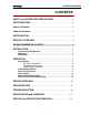
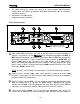
If you’re using the M-S Decoder:
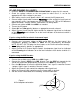
1. Connect the cardioid or omni MID mic to MIC 1 input.
2. Connect the figure 8 SIDE mic to MIC 2 input. Face the SIDE mic toward the left
side of the sound field (perpendicular to the axis of the MID mic). See Figure 1.
3. Press the M-S button to select the Mid-Side Mode. “Left” signal is routed to Channel
1 output. “Right” signal is routed to Channel 2 output.
4. Adjust the Channel 1 gain control for adequate mono signal level.
5. Adjust the Channel 2 gain control to vary the image width as desired.
6. See the section “More About M-S Decoding” for more information.
Figure 1
M-S microphone orientation
MID
SIDE