TRUE systems PRECISION 8 8-CHANNEL PRECISION MICROPHONE PREAMPLIFIER with M/S decoding and Direct Inputs OPERATION MANUAL Version 1.
SAFETY and OPERATING PRECAUTIONS Important Information: This symbol indicates the presence of dangerous voltage within the product enclosure that presents the risk of electric shock injury. When this symbol appears next to an operation discussed in this manual, only qualified technical personnel should perform that operation. This symbol indicates important operating or maintenance instructions that should be read carefully.
CERTIFICATIONS Declaration of Conformity – UL Sunrise Engineering and Design Inc. hereby declares the TRUE Systems PRECISION 8 has the following Underwriters Laboratories listing: • E212615 – “84GK Professional Audio/Video Equipment” Technical files are maintained at corporate headquarters of Sunrise Engineering and Design Inc., 8175 E. Slate Ridge Drive, Tucson, Arizona 85715, USA.
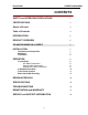
Precision 8 OPERATION MANUAL CONTENTS SAFETY and OPERATING PRECAUTIONS 2 CERTIFICATIONS 3 Owner’s Record 3 Table of Contents 4 INTRODUCTION 5 PRODUCT OVERVIEW 5 UP-AND-RUNNING IN A HURRY 6 INSTALLATION 7 7 7 8 OPERATION 8 8 8 8 9 10 11 13 DESIGN APPROACH 15 SPECIFICATIONS 15 TROUBLESHOOTING 16 REGISTRATION and WARRANTY 17 SERVICE and SUPPORT INFORMATION 18 Unpacking and Inspection Mounting Ventilation Connections AC Mains Connection Output Cable Connection Microphone Cable Conn
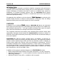
Precision 8 OPERATION MANUAL INTRODUCTION The PRECISION 8 is designed to provide the detailed, transparent sonic performance necessary for the most critical direct tracking and live sound applications. It includes a unique combination of functions that make it useful as a complete input system for standalone or PC-based recording systems. And, the PRECISION 8 has special features that provide the serious musician or recordist with useful tools to get the best sound more quickly and easily.
Precision 8 OPERATION MANUAL UP-AND-RUNNING IN A HURRY Read the “Safety and Operating Precautions” on page 2 of this manual. Connect to 120VAC, 60 Hz power sources only. (Consult factory for other options) After making sure the main power switch is off, connect the AC power cord. Connect output signal cables between PRECISION 8 and the analog line level inputs of your recorder, mixer, signal processor, etc. Use either the individual 1/4” TRS or DB25 eight-channel balanced output connectors.
Precision 8 OPERATION MANUAL About the Level and Peak-Hold Indicators: 1. SIG indicates that a signal is present on the channel. It illuminates when the signal level exceeds -24dBu. 2. +4 illuminates when the output signal reaches normal operating level of +4 dBu. 3. OL illuminates when the signal level exceeds +26 dBu, which is 5 dB below the overload point for the Precision 8. 4. The PEAK-HOLD indicators (PK,-3,-6) activate when the output signal level exceeds the level set on the PEAK REFERENCE switch.
Precision 8 OPERATION MANUAL equipment that emits strong electromagnetic fields. If the unit is to be permanently mounted in a high-vibration environment, you may wish to provide additional side or rear support to prevent possible distortion of the mounting ears. • Do not locate the unit where it is exposed to rain, moisture, or liquid spills. • Do not locate the unit where it is exposed to temperature extremes. • Do not mount the Power Supply Unit closer than one rack space from the preamp unit.
Precision 8 OPERATION MANUAL The DB25 and TRS output connectors are not electronically isolated. Therefore, if you chose to connect either one of the output connectors to an unbalanced input, the other connector will automatically be unbalanced. When connecting an output of the Precision 8 to an unbalanced input, you must connect the negative signal pin (pin 3 of the XLR or “ring” of the TRS) to the shield. Failure to do this will result in audible distortion.
Precision 8 OPERATION MANUAL Do not attempt to connect unbalanced microphones (with single-pin connectors) to the Precision 8. It is not intended to operate with this type of microphone. CAUTION: We recommend that you avoid “hot-patching” microphone inputs when using a patch bay at the microphone inputs of the Precision 8. Please TURN OFF phantom power and turn down the gain prior to connecting or re-patching microphone inputs routed through a patch bay.
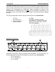
Precision 8 OPERATION MANUAL Front Panel Controls 4 3 OL PK 30 35 8 OL 40 -3 TRUE systems -6 Ø 50 55 2 SIG 35 30 OL 40 -3 45 48V +4 PK 1 MID ON 6 1 -6 Ø 50 SIG 30 35 -3 45 48V +4 64 16 PK 55 64 16 SIDE 2 -6 48V +4 Ø SIG 16 3 7 5 1 Phase reverse selector. Output signal polarity is reversed when the φ button is depressed. 2 Phantom power selector. Phantom power (+48V) is activated when the 48V button is depressed.
Precision 8 OPERATION MANUAL can provide accessory Output Attenuators in applications where this is necessary. Please consult the factory for assistance. 5 Signal Present indicator. The SIG indicator activates at approximately -24 dBu. 6 Operating level indicator. The +4 indicator activates when the output level reaches +4 dBu normal operating level. When the PEAK REFERENCE selector 9 is set to the -10 dBV position, the operating level indicator activates at -10 dBV output level.
Precision 8 OPERATION MANUAL More About M-S Decoding: M-S (Mid-Side) decoding is a particularly creative feature of the Precision 8. While the M-S microphone technique has been around for many years, the opportunity to use it is frequently limited by the need for specialty microphones and/or decoders. What is M-S? It is a stereo microphone placement technique that uses a center, forward-facing omni or cardioid mic (Mid) and a side-facing figure 8 mic (Side).
Precision 8 OPERATION MANUAL Optional Level Indicator Modes The Peak-Hold level indicators can operate in two modes. As supplied, only the OL and PK indicators will hold (after they are activated) until RESET is depressed. An optional mode is available which causes the -3 and -6 indicators to also hold until RESET is depressed. This mode can be helpful in live sound and recording applications where the Precision 8 is remotely located from the device(s) to which it is connected.
Precision 8 OPERATION MANUAL DESIGN APPROACH Precision 8 features a high-voltage composite architecture with discrete devices plus integrated circuits. The totally balanced, dual servo, dc-coupled design provides exceptional transient response, headroom, imaging and noise performance. Critical devices have been selected on the basis of extensive listening tests as well as engineering tests. Military grade, hand-matched components are utilized in critical circuit areas.
Precision 8 OPERATION MANUAL TROUBLESHOOTING Solution Symptom No signal output. Main power switch • is on, but no LED’s are illuminated. • Check AC power source and cord. Check fuses (pull fuse drawer next to power cord inlet) No signal output. Main power switch • is on and green power LED is • illuminated. • Check status of phantom power. Check continuity of mic and instrument cables. Check continuity of output cables. Output signal is distorted. Outputs • are connected for balanced operation.
Precision 8 OPERATION MANUAL Channel 1 signal can be heard in • Channel 2 output - and vice versa. Check status of M-S selector. It should be “out” for individual channel mode and “in” for Mid-Side mode. Channel 2 seems to have no output • when used with Channel 1 as a stereo pair • Check status of M-S selector. It should be “out” for individual channel mode and “in” for Mid-Side mode. Make sure the φ selectors for both Channels 1 and 2 are “out”.
Precision 8 OPERATION MANUAL repaired or replaced at the manufacturer’s option, free of charge. Supplementary shipping charges will apply to units returned to addresses outside the continental USA. All units returned to SUNRISE or authorized TRUE systems repair facility must be prepaid, insured and properly packaged. Purchaser must obtain a Return Authorization (RA) number from SUNRISE prior to returning a product.