
User guide


Precision 8 OPERATION MANUAL
12
can provide accessory Output Attenuators in applications where this is necessary.
Please consult the factory for assistance.
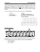
5 Signal Present indicator. The SIG indicator activates at approximately -24 dBu.
6 Operating level indicator. The +4 indicator activates when the output level reaches
+4 dBu normal operating level. When the PEAK REFERENCE selector 9 is set
to the -10 dBV position, the operating level indicator activates at -10 dBV output
level.
7 Mid-Side mode selector. When the ON button is depressed, Channel 1 output
becomes “Right” and Channel 2 output becomes “Left”. The Channel 1 gain control
adjusts the mono signal level applied to both the Left and Right outputs. The
Channel 2 gain control adjusts the stereo image width.
8 Gain control. This control adjusts the preamp gain over the range of 16 dB to 64
dB.
9 PEAK REFERENCE selector. This sets the level at which the Peak-Hold indicators
4 activate. It also changes the operating level indication 6 to -10 dBV operation
when the -10 dBV position is selected.
10 Peak-Hold reset. RESET clears the peak-hold indicators on all channels. NOTE: It
is normal for the Peak-Hold indicators to activate when phantom power is applied,
when AC power is applied, or when a new setting is made on the PEAK
REFERENCE selector - simply depress RESET to clear the indicators.
11 Direct inputs DI-1 and DI-2 are controlled by gain controls for channels 7 and 8,
respectively. The gain range for the direct inputs is from -4 dB to +44 dB.
12 AC power indicator. The green power LED indicates that the unit is on.
6464
4040
4545
5050
5555
1616 6464
3030
3535
4040
4545
5050
5555
1616 6464
3030
3535
4040
4545
5050
5555
+26+26
+22+22
RESETRESET
77
88
PEAK
REFERENCE
PRECISION
8
SIGSIG
+4+4
-6-6
48V48V
OLOL
PKPK
SIGSIG
+4+4
-6-6
-3-3
48V48V
OLOL
PKPK
DI 1DI 1 DI 2DI 2
+24+24
+20+20
+18+18
-10-10
dBVdBV
ØØ ØØ
-3-3
9
10
11
12