
User guide

Precision 8 OPERATION MANUAL
9
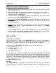
The DB25 and TRS output connectors are not electronically isolated. Therefore, if you
chose to connect either one of the output connectors to an unbalanced input, the other
connector will automatically be unbalanced. When connecting an output of the
Precision 8 to an unbalanced input, you must connect the negative signal pin (pin 3 of
the XLR or “ring” of the TRS) to the shield. Failure to do this will result in audible
distortion.
The wiring configuration used for the output connectors on the Precision 8 is:
For TRS:
• Tip is positive (+)
• Ring is negative (-)
• Sleeve is shield
For DB25:
This output connector is wired
according to the Tascam 8-channel
analog wiring configuration. DO NOT
USE TDIF CABLES.
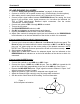
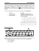
Microphone Connection:
MIC 1MIC 2MIC 3MIC 4MIC 5MIC 6
MIC 7MIC 8
Direct In
1
Direct In
2
MS
PIN 2 +
PIN 3 -
3 4
Microphone connection is made to standard XLR receptacles on the rear panel. The
wiring configuration used for the microphone connectors on the Precision 8 is:
• Pin 2 is positive (+)
• Pin 3 is negative (-)
• Pin 1 is shield