
Instruction Manual


SPEC SERIES www.truemfg.com
TEC_TM_141 | REV. A | EN06/30/2022 Page 10 of 24
Angle/Rod/Universal Tray Installation
(Kits #1, # 2 & #3)
Required Tools
• Flat Blade Screwdriver
• Rubber/Plastic Mallet
• Tape Measure
Installation
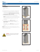
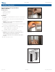
1. Thread the provided hardware into the holes on the cabinet
sidewall.
2. Slide the pilasters into position behind the threaded screws.
See figs. 1-3.
NOTE: Leave the screws loose for adjustment when
installing the tray slides.
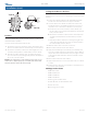
3. Verify the distance between the center holes of front and back
pilaster pairs is 24-5/8” (625mm). See fig. 4.
4. Verify the width between the pilasters. See figs. 5 and 6.
• ANGLE & ROD TRAYS: 18-1/8” (460 mm)
• UNIVERSAL TRAYS: 21-1/4” (540 mm)
5. Hook the tray slides into the pilasters. See figs. 7a-7c.
NOTE: When disassembling or changing tray slides, a
rubber mallet may be used to remove the
tray slides. Gently tap on the underside of the slide to
loosen it.
6. Tighten the pilaster screws.
Cabinet Setup (cont.)
Fig. 1. Pilaster installation on cabinet sidewall.
Fig. 2. Angle/rod tray pilaster installation; center
of cabinet rear.
Fig. 3. Universal tray pilaster installation; center
of cabinet rear.
24 5/8 inches
625.5 mm
Fig. 4. Measure between center holes of
each pair of front and back pilasters.