TRUE RESIDENTIAL® TR-30 / TR-36 I N S TA L L G U I D E A N D U S E R ' S M A N U A L PRESERVE THE MOMENT® TEC_TM_009 REV.
THANK YOU FOR YOUR PURCHA SE I N S TA L L AT I O N C H E C K L I S T To ensure no part of the installation process has been overlooked, complete the checklist below.
CONTENTS CABINET SETUP SAFETY INFORMATION & OWNERSHIP OWNERSHIP 6 SHELVING, BINS, DRAWERS 34 SAFETY PRECAUTIONS 6 REFRIGERATOR STORAGE 34 DISPOSAL OF OLD REFRIGERATOR 6 FREEZER STORAGE 35 CFC DISPOSAL 6 KICKPLATE INSTALLATION 36 REFRIGERATOR/FREEZER OPERATION PRIOR TO INSTALLATION SITE PREPARATION 8 ELECTRICAL REQUIREMENTS 10 ANTI-SWEAT FOAM END PANELS 10 WIRE RACK HANDLE FINISH APPLICATION (TR-30DZW) 11 REFRIGERATOR & FREEZER BASIC ELECTRONIC CONTROL OPERATIONS 38 SHOWROOM MODE
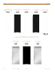
3 0 & 3 6 I N C H R E F R I G E R ATO R , F R E E Z E R & D U A L ZO N E CO L U M N 30" REFRIGERATOR BEVERAGE COLUMN 30" REFRIGERATOR COLUMN 30" REFRIGERATOR COLUMN 30" FREEZER COLUMN 30" DUAL ZONE WINE COLUMN STAINLESS GLASS DOOR STAINLESS SOLID DOOR STAINLESS GLASS DOOR STAINLESS SOLID DOOR STAINLESS GLASS DOOR x150 L U X URY R EF R IG ER AT ION W I T H C OMMER CI A L DN A .
S A F E T Y I N F O R M AT I O N & O W N E R S H I P OWNERSHIP SAFET Y PRECAUTIONS D I S P O S A L O F T H E O L D R E F R I G E R ATO R CFC DISPOSAL PRESERVE THE MOMENT® TEC_TM_009 REV.
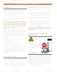
S A F E T Y I N F O R M AT I O N & O W N E R S H I P • DO NOT store or use gasoline or other flammable vapors and liquids in the vicinity of this or any other appliance. OWNERSHIP This appliance is not intended for use by persons (including children) with reduced physical, sensory or mental capabilities, or lack of experience and knowledge, unless they have been given supervision or instruction concerning use of the appliance by a person responsible for their safety.
P R I O R TO I N S TA L L AT I O N S I T E P R E PA R AT I O N ELEC TRICAL REQUIREMENTS A N T I -S W E AT F O A M E N D PA N E L S W I R E R A C K H A N D L E F I N I S H A P P L I C AT I O N ( T R-3 0 DZ W ) PRESERVE THE MOMENT® TEC_TM_009 REV.
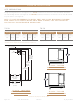
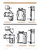
P R I O R TO I N S TA L L AT I O N SITE PREPAR ATION Rough Opening dimensions. (See figure 1). For FLUSH installations the front face of the unit will be flush with the surrounding cabinets. (See figure 2). For PROUD (Standard) installations, the front face of the unit will extend beyond cabinets. (See figure 3). NO T E: I T I S NO T R EC OMMEND ED T O IN S TA L L UNI T S SID E BY SID E W I T H HING E S T OUCHING E A CH O T HER .
TR-30DZW-R-SG-A TR-30DZW-R-SG-A T TR P R I O R TO I N S TA L L AT I O N R R 15/32" 3030 15/32" 774mm 774mm 11/16" 2020 11/16" 525mm 525mm 2 9/16" 2 9/16" 65mm65mm 30" 36" 762mm 915mm 27 29/32" 27 29/32" 709mm 709mm 25 25/32" 25 25/32" 655mm 655mm 135° 135° 9/16" 2929 9/16" 751mm 751mm 83 15/16" 83 15/16" 2132mm 2132mm 25/32" 2323 25/32" 604mm 604mm 1/4" 5555 1/4" 1403mm 1403mm 67 29/32" 1725mm DOOR HEIGHT 23 25/32" 23 25/32" 604mm 604mm 72 5/8"72 5/8" 1845mm 1845mm 15/32" 3131 15/32" 799mm 79
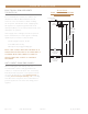
P R I O R TO I N S TA L L AT I O N ELEC TRIC AL REQUIREMENT S TR-30/ TR-36 For all built-in models, the electrical supply should be located within the shaded area shown in the illustration. Follow the National Electrical Code and local codes and ordinances when installing the receptacle. A dedicated circuit, supplying only this appliance is required. A ground fault circuit interrupter (GFCI) is not recommended and may cause interruption of operation.
P R I O R TO I N S TA L L AT I O N WIRE R ACK HANDLE FINISH APPLIC ATION ( TR-30DZ W) See finish (e.g., paint or stain) for application instructions and drying / curing times. Drying / Curing times vary by finish. Follow recommended guidelines associated with treating unfinished natural cherry wood.
NOTES Page 12 of 56 T RUE RE S ID E N TI A L ® 03/31/2022 TEC_TM_009 REV.
I N S TA L L AT I O N P L A N V I E W S T R-3 0 / T R- 4 2 T R-3 0 / T R- 4 8 T R-3 0 / T R-3 0 T R-3 0 / T R-3 0 / T R-3 0 T R-3 6 R E F / T R-3 6 R E F T R-3 6 R E F / T R-3 0 R E F PRESERVE THE MOMENT® TEC_TM_009 REV.
I N S TA L L AT I O N P L A N V I E W S TR-30 / TR-42 TR-42,30DZW R Flush Opening Dimensions Proud Opening Dimensions Width Depth Height Width Depth Height 721/4" 25 25⁄32" 841/4" 713/4" 23 25⁄32" 84" 23 25/32" 604mm PROUD INSTALL D im e n si o n s m ay v a r y by ± 1 / 8 " (3. 2 m m) TR-42,30DZW ROUG H OPENING & ELEC TRIC AL ARE A FLUSH VS .
I N S TA L L AT I O N P L A N V I E W S TR-30 / TR-48 TR-48,30DZW R Flush Opening Dimensions Proud Opening Dimensions Width Depth Height Width Depth Height 781/4" 25 25⁄32" 841/4" 773/4" 23 25⁄32" 84" 23 25/32" 604mm PROUD INSTALL D im e n si o n s m ay v a r y by ± 1 / 8 " (3. 2 m m) FLUSH VS .
I N S TA L L AT I O N P L A N V I E W S TR-30 / TR-30 TR-30REF,30DZW R Flush Opening Dimensions Proud Opening Dimensions Width 601/4" Depth Height Width Depth Height 25 25⁄32" 841/4" 593/4" 23 25⁄32" 84" 23 25/32" 604mm PROUD INSTALL D im e n si o n s m ay v a r y by ± 1 / 8 " (3. 2 m m) FLUSH VS .
I N S TA L L AT I O N P L A N V I E W S TR-30 / TR-30 / TR-30 Flush Opening Dimensions Proud Opening Dimensions Width Depth Height Width 901/4" 25 25⁄32" 841/4" 893/4" R TR-30REF,30FRZ,30DZW Depth Height 23 25⁄32" 84" D im e n si o n s m ay v a r y by ± 1 / 8 " (3. 2 m m) 23 25/32" 604mm PROUD INSTALL FLUSH VS .
I N S TA L L AT I O N P L A N V I E W S TR-36REF / TR-36REF Flush Opening Dimensions Proud Opening Dimensions Width Depth Height Width Depth Height 721/4" 25 25⁄32" 841/4" 713/4" 23 25⁄32" 84" D im e n si o n s m ay v a r y by ± 1 / 8 " (3. 2 m m) FLUSH VS .
I N S TA L L AT I O N P L A N V I E W S TR-36REF / TR-30REF Flush Opening Dimensions Proud Opening Dimensions Width Depth Height Width Depth Height 661/4" 25 25⁄32" 841/4" 653/4" 23 25⁄32" 84" D im e n si o n s m ay v a r y by ± 1 / 8 " (3. 2 m m) FLUSH VS .
NOTES Page 20 of 56 T RUE RE S ID E N TI A L ® 03/31/2022 TEC_TM_009 REV.
I N S TA L L AT I O N U N C R AT I N G A N T I -T I P B R A C K E T I N S T A L L A T I O N LEVELING THE UNIT J O I N I N G K I T I N S TA L L AT I O N PRESERVE THE MOMENT® TEC_TM_009 REV.
I N S TA L L AT I O N UNCR ATING R EQUIR ED T O O L S • Drill or ratchet • 7/16" Deep well socket • Cutting Tool WARNING! TIP OVER HAZARD. Unit poses a tipping hazard when moving or during installation. Do not move the unit without the shipping brackets installed. Do not remove the appliance from the pallet without assistance. Failure to do so may result in property damage, personal injury, or death. FIG. 1. Inspect the exterior packaging for visible damage.
I N S TA L L AT I O N UNCR ATING (CONT.) 3. Closely inspect the unit’s interior for damage (e.g., scratches by shelving or damage to the door seal). See fig. 5. NO T E: D O NO T R EMO V E T HE IN T ER IO R PA CK A GING. 4. Move the unit as close as possible to the final installation location. NO T E: SECUR E T HE D O O R BEF O R E MO V ING T HE UNI T T O I T S F IN A L L O C AT ION (SEE F IG. 6). R EPA CK A G E T HE UNI T W I T H T HE E X T ER IO R PA CK A GING A S NEED ED BEF O R E MO V ING T HE UNI T.
I N S TA L L AT I O N UNCR ATING (CONT.) 6. Remove the condensate drain pan. Set the drain pan aside. See fig. 9. 7. Slightly raise the rear leveling leg rollers. Turn the front adjustment screw 1/4-1/2 turn clockwise. See fig. 10. 8. With assistance, pull the unit off the back of the pallet. Then, remove the pallet and Carefully guide the unit to a fully upright position. See fig. 11. FIG. 9. Remove the drain pan before pulling the appliance off the skid.
987036 RUE RESIDENTIAL REFRIGERATION 5.19.17 AL BR ACKE T INS TALL ATION I NPSATGAEL LTAI T ILO EN T KIT: (Figure 1.1) screws ” screws rs UPRIG HT 2. Using the bracket as a guide, drill pilot holes into the wall/floor. It is recommended to secure the bracket ANTI-TIP BR joists ACKE INS TALL ATION to as many floor andTwall studs as possible. K I T C ON T EN T3.SUsing the provided screws and washers, secure the P R O CEDUR E bracket to the wall/floor.
I N S TA L L AT I O N LE VELING THE UNIT It is very important that the refrigerator sits level. This will insure that the doors will align and seal properly and that the drain pans will not spill over. P R O CEDUR E 1. Place a level on the interior floor. Check and adjust for level from front to back, also check and adjust for level from right to left. 2. Adjust the fronts using a set of pliers or a wrench. (See Figure 1). 3. Adjust the rear using a 7/16" socket and ratchet.
I N S TA L L AT I O N JOINING KIT INS TALL ATION 987036 TRUE RESIDENTIAL REFRIGERATION 5.19.17 AL ANTI-TIP ACKE T INS TALL ATION Kit Sizes: 60" (1524 mm)UPRIG / 72" HT (1828.8 mm)BR / 78" (1981.2 mm) / 90" (2286 mm) K I T C ON T EN T S • • • • • 2. Using the bracket as a guide, drill pilot holes into the WARNING! TIP OVER HAZARD. wall/floor. It is recommended to secure the bracketA ANTI-TIP BR ACKE T KIT: child or in (1) Joining property damage or bodily harm. Follow 3.
I N S TA L L AT I O N JOINING KIT INS TALL ATION (CONT.) Kit Sizes: 60" (1524 mm) / 72" (1828.8 mm) / 78" (1981.2 mm) / 90" (2286 mm) P R O CEDUR E 1. Remove the reed switch bracket. See figs. 2 and 3. 1 2. Remove the reed switch cover, and then disconnect the reed switch. See figs. 4 and 5. NO T E: IF F OUR (4) W IR E S A R E C ONNEC T ED T O T HE R EED SW I T CH, BE SUR E T O CL E A R LY L A BEL T HE W IR E S ’ O R IGIN A L L O C AT ION S BEF O R E DI S C ONNEC T ING T HE R EED SW I T CH.
I N S TA L L AT I O N JOINING KIT INS TALL ATION (CONT.) Kit Sizes: 60" (1524 mm) / 72" (1828.8 mm) / 78" (1981.2 mm) / 90" (2286 mm) 7. Install anti-sweat foam end panels on the joined units’ sides where the cabinets will meet. See figs. 13 and 14. 8. Position the units in front of the final installation location. Then, level the units. 9. Verify the fronts of the units are flush at the seams and the gap(s) between the units is (are) consistent from top to bottom. See figs. 15 and 16. FIG. 11.
I N S TA L L AT I O N JOINING KIT INS TALL ATION (CONT.) Kit Sizes: 60" (1524 mm) / 72" (1828.8 mm) / 78" (1981.2 mm) / 90" (2286 mm) 14. Walk the joined units into their final installation location. 15. Verify the level of the cabinets. Level the units as needed. 16. Restore power to the units and turn the units on. 17. After 3 minutes of runtime, open the doors individually and verify correct door switch operation. When operating correctly, the following should occur: FIG. 15.
CABINET SETUP S H E LV I N G R E F R I G E R ATO R S TO R A G E FREEZER STORAGE K I C K P L AT E I N S TA L L AT I O N PRESERVE THE MOMENT® TEC_TM_009 REV.
CABINET SETUP SHELVING , BINS , DR AWERS All shelving and door bins come packaged inside the unit. (See Figure 1) FIG. 1. Interior packaging. REFRIG ER ATOR S TOR AG E G L A S S SHELV E S Remove the top foam piece holding the glass shelves. Carefully remove shelves and set aside. (See Figure 2). Remove all other packing material. To install, insert glass shelf into the shelf standards on the back wall, with the front tilted upward, and then lower the front until it stops. (See Figure 3).
CABINET SETUP D R AW ER S To remove a drawer, pull drawer forward until it stops. Use a Phillips screw driver to remove the two (2) screws securing the drawer to the slides, then lift the drawer up and out of unit. (See Figure 8). To reinstall, pull drawer slides all the way forward on unit, and then slide the drawer onto the slides until the hook on the back of the slide is over top of the drawer, reinstall the screws using the Phillips screw driver. FIG. 8. Drawer slide screw locations.
CABINET SETUP KICKPL ATE INS TALL ATION The kickplate is shipped with the unit but not attached to allow access to level the unit. Once the unit is level, the kickplate attaches to the front, bottom of the unit with magnets located on the left and right. FIG. 1. Kickplate. Page 34 of 56 FIG. 2. Kickplate Magnets. T RUE RE S ID E N TI A L ® 03/31/2022 FIG. 3. Installed kickplate. TEC_TM_009 REV.
R E F R I G E R ATO R / F R E E Z E R O P E R AT I O N R E F R I G E R ATO R A N D F R E E Z E R B A S I C E L EC T R O N I C O P E R AT I O N S SHOWROOM MODE PRESERVE THE MOMENT® TEC_TM_009 REV.
R E F R I G E R ATO R / F R E E Z E R O P E R AT I O N BA SIC ELEC TRONIC CONTROL OPER ATIONS UNI T ON / O F F P L E A SE NO T E T H AT T HOUGH P O S SIBL E T O DI SP L AY T EMP ER AT UR E S IN FA HR ENHEI T O R CEL SIU S, IN MO S T C A SE S FA HR ENHEI T R E A DING S A R E SHO W N IN T HI S M A NUA L . All units are shipped in ON Mode.
R E F R I G E R ATO R / F R E E Z E R O P E R AT I O N TEMPER AT URE AD JUS TMENT To adjust set-point, press DOWN or UP key on control panel in multiple key strokes until the desired setpoint is achieved. Each key stroke equals a one degree change and is accompanied by an audible beep. When the desired set-point is reached wait 5 seconds until display resumes “HOME” screen. T HE T EMP ER AT UR E R A NG E IN A R EF R IG ER AT O R Z ONE I S + 3 4°F (+1°C) T O + 4 2 °F (+ 6°C).
R E F R I G E R ATO R / F R E E Z E R O P E R AT I O N MODE NAVIG ATION The following pages illustrate unique customer input operations performed at the control panel. The input operations described are: HOLIDAY Mode, Temperature Unit Selection Mode and VACATION MODE. • Freezer defrosting functions will convert to a fixed time base sequence.
R E F R I G E R ATO R / F R E E Z E R O P E R AT I O N ACCENT LIG HTING S YS TEM All models are equipped with an accent lighting system in the refrigerator and or freezer compartment(s). To energize the accent lighting system, press the LIGHT key, and navigate to the corresponding compartment, DOOR or ON will appear in the LCD indicating the accent lights are enabled.
R E F R I G E R ATO R / F R E E Z E R O P E R AT I O N AL ARM NAVIG ATION (D OOR A JAR AL ARM FE AT URE ON/OFF) All Residential Series units are equipped with a door ajar alarm feature. To enable the door ajar alarm, press the ALARM key on the control panel and “DOOR ALARM IS ON” will appear in the LCD indicating the alarm is enabled. With the alarm enabled, the notification icons will appear and an audible alarm will beep continuously whenever a door is left open for more than 5 minutes.
R E F R I G E R ATO R / F R E E Z E R O P E R AT I O N NOTIFIC ATION ALERT S The diagrams on these pages illustrate what a customer may see in the LCD if the appliance needs attention. NO T IF IC AT ION A L ER T S 38°F MODE LIGHT ALARM 38°F •defrost •high temp •showroom mode •communication •service •door TEC_TM_009 REV.
R E F R I G E R ATO R / F R E E Z E R O P E R AT I O N SHOWRO OM MODE When in Showroom Mode all cooling and defrosting functions are disabled, but the lighting system and door ajar alarm system remain operational, and the LCD will show the set-points. NO T E: F O R D EMON S T R AT ION P UR P O SE S, A L L T HE N AV IG AT ION MENU S A R E DI SP L AY ONLY A ND IN A C T I V E .
D U A L ZO N E O P E R AT I O N DUAL ZONE B A S I C E L EC T R O N I C O P E R AT I O N S SHOWROOM MODE PRESERVE THE MOMENT® TEC_TM_009 REV.
D U A L ZO N E O P E R AT I O N BA SIC ELEC TRONIC CONTROL OPER ATIONS UNI T ON / O F F P L E A SE NO T E T H AT T HOUGH P O S SIBL E T O DI SP L AY T EMP ER AT UR E S IN FA HR ENHEI T O R CEL SIU S, IN MO S T C A SE S FA HR ENHEI T R E A DING S A R E SHO W N IN T HI S M A NUA L . All units are shipped in ON Mode. When electricity is supplied to the appliance, a short power up diagnostics test is initiated followed by one audible beep, the lights energizing and temperature readings appearing in the LCD.
D U A L ZO N E O P E R AT I O N TEMPER AT URE AD JUS TMENT To adjust set-point, press the ZONE button to highlight the zone for adjustment. Once the zone is highlighted, press DOWN or UP key on the control panel in multiple key strokes until the desired set-point is achieved. Each key stroke equals a one degree change and is accompanied by an audible beep. When the desired set-point is reached, press the ZONE button to return to “HOME” screen. NO T E: T HE T EMP ER AT UR E R A NG E S F R OM 4 0 °F (4 .
D U A L ZO N E O P E R AT I O N MODE NAVIG ATION The following pages illustrate unique customer input operations performed at the control panel. The input operations described are: HOLIDAY Mode, Temperature Unit Selection Mode and VACATION MODE. • Freezer defrosting functions will convert to a fixed time base sequence.
D U A L ZO N E O P E R AT I O N ACCENT LIG HTING S YS TEM COLOR CHANG E All models are equipped with an accent lighting system in the refrigerator and or freezer compartment(s). To change colors of the LED’s, press the light button once until you see “CHANGE COLOR”. Press the “LIGHT” button once and release to start cycling through TruLumina ®. Press the “LIGHT” button again to hold the color option you desire.
D U A L ZO N E O P E R AT I O N AL ARM NAVIG ATION (D OOR A JAR AL ARM FE AT URE ON/OFF) All Residential Series units are equipped with a door ajar alarm feature. To enable the door ajar alarm, press the ALARM key on the control panel and “DOOR ALARM IS ON” will appear in the LCD indicating the alarm is enabled. With the alarm enabled, the notification icons will appear and an audible alarm will beep continuously whenever a door is left open for more than 5 minutes.
D U A L ZO N E O P E R AT I O N NOTIFIC ATION ALERT S The diagrams on these pages illustrate what a customer may see in the LCD if the appliance needs attention. NO T IF IC AT ION A L ER T S 55°F ZONE 45°F MODE LIGHT ALARM 55°F 45°F •defrost •high temp •showroom mode •communication •service error required •door alarm •zone 1 upper high temp •zone 2 lower high temp TEC_TM_009 REV.
D U A L ZO N E O P E R AT I O N SHOWRO OM MODE When in Showroom Mode all cooling and defrosting functions are disabled, but the lighting system and door ajar alarm system remain operational, and the LCD will show the set-points. NO T E: F O R D EMON S T R AT ION P UR P O SE S, A L L T HE N AV IG AT ION MENU S A R E DI SP L AY ONLY A ND IN A C T I V E .
MAINTENANCE, CARE & CLEANING S TA I N L E S S S T E E L EQ U I P M E N T C A R E A N D C L E A N I N G GENERAL MAINTENANCE CO N D E N S AT I O N D ATA TA G REMOVING THE DOORS CO N TA C T U S WARR ANT Y PRESERVE THE MOMENT® TEC_TM_009 REV.
MAINTENANCE, CARE & CLEANING S TAINLE SS S TEEL EQUIPMENT C ARE AND CLE ANING NOTE! Do not use any steel wool, abrasive or chlorine based products to clean stainless steel surfaces. STAINLESS STEEL OPPONENTS There are three basic things which can break down your stainless steel’s passivity layer and allow corrosion to rear its ugly head. • Scratches from wire brushes, scrapers, and steel pads are just a few examples of items that can be abrasive to stainless steel’s surface.
MAINTENANCE, CARE & CLEANING S TAINLE SS S TEEL EQUIPMENT C ARE AND CLE ANING 8 TIPS TO HELP PREVENT RUST ON STAINLESS STEEL • Maintain the Cleanliness of Your Equipment – Avoid build-up of hard stains by cleaning frequently. Use cleaners at the recommended strength (alkaline chlorinated or non-chloride). • Use the Correct Cleaning Tools – Use non-abrasive tools when cleaning your stainless steel products. The stainless steel’s passive layer will not be harmed by soft cloths and plastic scouring pads.
MAINTENANCE, CARE & CLEANING G ENER AL M AINTENANCE REMOVING THE DO ORS Keeping the condenser coil clean will minimize required service and lower electrical cost. The condenser coil is accessible from the front. The condenser coil should be cleaned by removing dust and other build-up from the tube assembly with vacuum or a cleaning rag. When properly cleaned you should be able to see through the tube assembly. Warranty does not cover cleaning the condenser coil. Open the top louver grill.
TT R RUUE E RREESSI IDDEENNTTIIAALL®® SS E R I E S LL II M MIITTEEDD W WAARRRRAANNTTY YS ST A TT AE TM EM ET NT EN LIMITED 30 DAY COSMETIC WARRANT Y Stainless steel doors, handles, and shelves are warranted to be free from defective materials or workmanship for a period of thirty (30) days from the date of original retail purchase. Any defects must be reported to the selling dealer within thirty (30) days from the date of original retail purchase.
CONTACT US true-residential.com | t o ll f r e e 8 8 8 .616. 878 3 BP_183821_03.22 636.240.2400 T RUE RE S ID E N TI A L ® 03/31/2022 TEC_TM_009 REV.