TRUE RESIDENTIAL® 3 6 I N C H B U I LT- I N B O T T O M F R E E Z E R I N S TA L L G U I D E & U S E R ' S M A N U A L PRESERVE THE MOMENT® TEC_TM_151 | REV.
THANK YOU FOR YOUR PURCHA SE I N S TA L L AT I O N C H E C K L I S T To ensure no part of the installation process has been overlooked, complete the checklist below.
TA B L E O F CO N T E N T S SAFETY INFORMATION & OWNERSHIP ELECTRONIC CONTROL OPERATION SAFETY WARNINGS & PRECAUTIONS 6 USER INTERFACE 38 PROPER DISPOSAL OF THE CABINET 7 SET POINT MENU 39 OWNERSHIP 8 ICE MENU 40 SERIAL LABEL LOCATION 8 MODE MENU 41 SERVICE REPORT 42 LIGHT MENU 43 DOOR AJAR ALARM 44 SHOWROOM MODE 45 SYSTEM NOTIFICATIONS 46 SITE PREPARATION ROUGH OPENINGS & PLAN VIEWS 10 ANTI-SWEAT FOAM END PANELS 12 ELECTRICAL SAFETY & INSTALLATION REQUIREMENTS 13 WATER SU
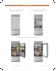
THE TRUE 36RBF 36" BUILT-IN BOT TOM FREE ZER 36 " BU ILT-IN BOT TOM FREE ZER STAINLESS SOLID D O OR STAINLESS GL ASS D O OR L U X URY R EF R IG ER AT ION W I T H C OMMER CI A L DN A . Page 4 of 56 T RU E R E S ID E N T I A L® 04/01/2022 TEC_TM_151 | REV.
S A F E T Y I N F O R M AT I O N & O W N E R S H I P SAFET Y WARNINGS & PRECAUTIONS CO R R EC T D I S P O S A L O F O L D R E F R I G E R ATO R OWNERSHIP S E R I A L L A B E L LO C AT I O N PRESERVE THE MOMENT® TEC_TM_151 | REV.
S A F E T Y I N F O R M AT I O N & O W N E R S H I P HOW TO M AINTAIN YOUR TRUE REFRIG ER ATOR TO RECEIVE THE MOS T EFFICIENT AND SUCCE SSFUL OPER ATION You have selected one of the finest commercial refrigeration units made. It is manufactured under strict quality controls with only the best quality materials available. Your TRUE cooler, when properly maintained, will give you many years of trouble-free service.
S A F E T Y I N F O R M AT I O N & O W N E R S H I P • D O NO T store explosive substances such as aerosol cans with a flammable propellant in this appliance. C ABINE T DISP OSAL WARNING DANGER! RISK OF CHILD ENTR APMENT • Keep fingers out of the "pinch point" areas; clearances between the doors and cabinet are necessarily small; be careful closing doors when children are in the area.
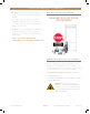
S A F E T Y I N F O R M AT I O N & O W N E R S H I P OWNERSHIP SERIAL L ABEL LO C ATION To ensure that your unit works properly from the first day, it must be installed properly. We highly recommend a trained refrigeration mechanic and electrician install your True equipment. The cost of a professional installation is money well spent. The serial label is located on the upper right wall of the freezer drawer. See fig. 1.
S I T E P R E PA R AT I O N ROUGH OPENINGS & PL AN VIEWS A N T I -S W E AT F O A M E N D PA N E L S E L EC T R I C A L S A F E T Y & I N S TA L L AT I O N R EQ U I R E M E N T S W AT E R S U P P LY R E Q U I R E M E N T S PRESERVE THE MOMENT® TEC_TM_151 | REV.
S I T E P R E PA R AT I O N ELECTRICAL AREA SITE PREPAR ATION Due to the weight of this unit, True recommends consulting a flooring expert prior to installation. The flooring beneath the unit should be rated to support ≥150 lbs/ft 2 (732.36 kg/m2).
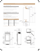
S I T E P R E PA R AT I O N ROUG H OPENINGS & PL AN VIEWS TR-36RBF / TR-36RBF Flush installation: The front face of the unit is flush with the surrounding cabinets Proud (standard) Installation: The front face of the unit extends beyond the surrounding cabinets Rough Opening Dimensions Flush Install Proud Install Width 72-1/4" (1835.15 mm) 71-3/4" (1822.45 mm) Depth 25-25/32" (654.84 mm) 23-25/32" (604.04 mm) Height 84-1/4" (2139.95 mm) 84" (2,133.
S I T E P R E PA R AT I O N N O T E: D IMENSI O NS M AY VA RY BY ± 1 / 8 ” (3.175 m m) ANTI-SWE AT FOA M END PANEL S When installing two or more True units side-by-side, be sure to leave at least a 5/8” (15.88 mm) gap between the cabinets, or install foam pads between the cabinets and on any side with 0” clearance, to prevent moisture from developing on applications. If installing anti-sweat foam end panels, True recommends applying a panel to each of the units being joined together.
S I T E P R E PA R AT I O N True will not warranty any refrigerator/freezer that has been connected to an extension cord. ELEC TRIC AL SAFE T Y Power Supply: 115VAC, 60hz Circuit Breaker: 15 Amp Receptacle: 3-Prong Grounding-Type • For all built-in models, the electrical supply should be located within the indicated shaded area shown in the figure below. • Be sure to follow the National Electrical Code, as well as local codes and ordinances, when installing the receptacle.
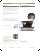
S I T E P R E PA R AT I O N P OWER CORD INSTALLATION Fully seat the power cord into the cabinet receptacle until it locks in position. See fig. 1. REMOVAL Depress the red button. See fig. 2. FIG. 1. Fully insert the power cord into the receptacle. Page 14 of 56 T RU E R E S ID E N T I A L® 04/01/2022 FIG. 2. Push the red button to remove the plug. TEC_TM_151 | REV.
S I T E P R E PA R AT I O N WATER SUPPLY REQUIREMENT S The unit comes with 20” (508 mm) of polyethylene tubing with a 1/4” O.D. push connector for customer attachment. Before installing your unit, prepare the water supply line. Please see plumbing requirements in the plumbing requirements table. • Purge the water line prior to final connection to the unit. This removes any debris present in the line. FIG. 1. Water line connection.
NOTES Page 16 of 56 T RU E R E S ID E N T I A L® 04/01/2022 TEC_TM_151 | REV.
I N S TA L L AT I O N U N C R AT I N G A N T I -T I P B R A C K E T I N S T A L L A T I O N LEVELING W AT E R F I LT E R I N S TA L L AT I O N & P E R F O R M A N C E D ATA K I C K P L AT E I N S TA L L AT I O N J O I N I N G K I T I N S TA L L AT I O N PRESERVE THE MOMENT® TEC_TM_151 | REV.
I N S TA L L AT I O N UNCR ATING R EQUIR ED T O O L S • Drill or ratchet • 7/16" Deep well socket • Cutting Tool WA R NING! T IP O V ER H A Z A R D. Unit poses a tipping hazard when moving or during installation. Do not move the unit without the shipping brackets installed. Do not remove the appliance from the pallet without assistance. Failure to do so may result in property damage, personal injury, or death. FIG. 1. Inspect the exterior packaging for visible damage.
I N S TA L L AT I O N UNCR ATING (CONT.) 3. Closely inspect the unit’s interior for damage (e.g., scratches by shelving or damage to the door seal). See fig. 5. NO T E: D O NO T R EMO V E T HE IN T ER IO R PA CK A GING. 4. Move the unit as close as possible to the final installation location. NO T E: SECUR E T HE D O O R BEF O R E MO V ING T HE UNI T T O I T S F IN A L L O C AT ION (SEE F IG. 6). R EPA CK A G E T HE UNI T W I T H T HE E X T ER IO R PA CK A GING A S NEED ED BEF O R E MO V ING T HE UNI T.
I N S TA L L AT I O N UNCR ATING (CONT.) 6. Remove the condensate drain pan. Set the drain pan aside. See fig. 9. 7. Slightly raise the rear leveling leg rollers. Turn the front adjustment screw 1/4-1/2 turn clockwise. See fig. 10. 8. With assistance, pull the unit off the back of the pallet. Then, remove the pallet and Carefully guide the unit to a fully upright position. See fig. 11. FIG. 9. Remove the drain pan before pulling the appliance off the skid.
TRUE RESIDENTIAL REFRIGERATION 987036 5.19.17 AL TIP BR ACKE T INS TALL ATION KE T KIT: cket (Figure 1.1) /16” screws – 2” screws I N S TA L L AT I O N 2. Using the bracket as a guide, drill pilot holes into the recommended to secure the bracketP R O CEDUR E ANTI-TIP BRwall/floor. ACKEItTisINS TALL ATION to as many floor joists and wall studs as possible. K I T C ON T EN T S 1. Measure and mark the depth of the bracket’s placement in the installation location. 3.
I N S TA L L AT I O N LE VELING It is important that your unit is level. This ensures the doors align and seal correctly and drain pans do not spill over. P R O CEDUR E 1. Place a level on the interior floor on the unit. Check the level back-to-front and side-to-side. See fig. 1 for leveling adjustment locations. 2. Adjust the front leveling legs as needed with pliers or an adjustable wrench. 3. Adjust the rear leveling legs as needed with a 7/16” socket. Turn clockwise to raise the rear of the unit.
I N S TA L L AT I O N WATER FILTER INS TALL ATION & PERFORM ANCE DATA The water filter filters sediment and removes unpleasant taste and odor. Install the provided water filter before using the icemaker. The unit will not make ice until the water filter is installed. P R O CEDUR E 1. Remove the kickplate. See fig. 1. FIG. 1. Pull the kickplate from the cabinet. 2. Insert the provided water filter (see fig. 2) and rotate the filter clockwise. (See figs. 3 and 4). 3. Reinstall the kickplate.
1,2-DCA (see 1,2-DICHLOROETHANE)* 1,1-DCE (see 1,1-DICHLOROETHYLENE)* DIBROMOCHLOROMETHANE (TTHM; Chlorodibromomethane)* DIBROMOCHLOROPROPANE (DBCP)* o-DICHLOROBENZENE (1,2 Dichlorobenzene)* p-DICHLOROBENZENE (para-Dichlorobenzene) 1,2-DICHLOROETHANE (1,2-DCA)* 1,1-DICHLOROETHYLENE (1,1-DCE)* CIS-1,2-DICHLOROETHYLENE* TRANS-1,2- DICHLOROETHYLENE* 1,2-DICHLOROPROPANE (Propylene Dichloride)* CIS-1,3- DICHLOROPROPYLENE* DINOSEB* EDB (see ETHYLENE DIBROMIDE)* ENDRIN Entamoeba (see CYSTS) ESTRONE ETHYLBENZENE* E
I N S TA L L AT I O N KICKPL ATE INS TALL ATION INSTALLATION The kickplate (see fig. 1) is shipped unattached to the unit to allow easy access for leveling the unit. The kickplate attaches to the unit with magnets (see fig. 2) located on either side at the bottom of the unit. After leveling the unit, position the kickplate at the bottom of the unit’s front. See fig. 3. REMOVAL Pull the kickplate away from the unit. FIG. 1. The kickplate. TEC_TM_151 | REV. B | EN FIG. 2. The magnets. One side shown.
987036 I N S TREFRIGERATION A L L AT I O N TRUE RESIDENTIAL 5.19.17 AL JOINING HT ANTI-TIP KIT UPRIG INS TALL ATIONBR ACKE T INS TALL ATION the bracket as a guide, drill pilot holes into the BR(1828.8 ACKE T mm) KIT: / 78" (1981.2 mm)2./ Using Kit Sizes: 60" (1524ANTI-TIP mm) / 72" 90" (2286 mm) K I T C ON T EN T S • • • • wall/floor. It is recommended to secure the bracket • One (1) anti-tip bracket (Figure 1.
I N S TA L L AT I O N JOINING KIT INS TALL ATION (CONT.) Kit Sizes: 60" (1524 mm) / 72" (1828.8 mm) / 78" (1981.2 mm) / 90" (2286 mm) NO T E: IF F OUR (4) W IR E S A R E C ONNEC T ED T O T HE R EED SW I T CH, BE SUR E T O CL E A R LY L A BEL T HE W IR E S ’ O R IGIN A L L O C AT ION S BEF O R E DI S C ONNEC T ING T HE R EED SW I T CH. W IR E L O C AT ION I S CR I T IC A L T O T HE C A BINE T ’ S OP ER AT ION. SEE F IG. 5. 1 2 3 4 3. Remove the reed switch wire from the rainshield. See figs. 6 and 7.
I N S TA L L AT I O N JOINING KIT INS TALL ATION (CONT.) Kit Sizes: 60" (1524 mm) / 72" (1828.8 mm) / 78" (1981.2 mm) / 90" (2286 mm) 7. Install anti-sweat foam end panels on the joined units’ sides where the cabinets will meet. See figs. 13 and 14. 8. Position the units in front of the final installation location. Then, level the units. 9. Verify the fronts of the units are flush at the seams and the gap(s) between the units is (are) consistent from top to bottom. See figs. 15 and 16. FIG. 11.
I N S TA L L AT I O N JOINING KIT INS TALL ATION (CONT.) Kit Sizes: 60" (1524 mm) / 72" (1828.8 mm) / 78" (1981.2 mm) / 90" (2286 mm) 14. Walk the joined units into their final installation location. 15. Verify the level of the cabinets. Level the units as needed. 16. Restore power to the units and turn the units on. 17. After 3 minutes of runtime, open the doors individually and verify correct door switch operation. When operating correctly, the following should occur: FIG. 15.
NOTES Page 30 of 56 T RU E R E S ID E N T I A L® 04/01/2022 TEC_TM_151 | REV.
CABINET SETUP D O O R I N S TA L L AT I O N & R E M O VA L R E F R I G E R ATO R S TO R A G E FREEZER STORAGE ICEMAKER PRESERVE THE MOMENT® TEC_TM_151 | REV.
CABINET SETUP D O OR INS TALL ATION & REMOVAL INSTALLATION 1. Hold the door perpendicular (90°) to the opening. 2. Align the hinge posts with the hinges. 3. Carefully lower the door into place. REMOVAL If door removal is necessary, see instructions below. 1. Open the door 90°. 2. Lift the door straight up off the hinges. FIG. 1. The unit with the door closed. FIG. 2. Carefully lift the door off its hinges. Page 32 of 56 T RU E R E S ID E N T I A L® 04/01/2022 TEC_TM_151 | REV.
CABINET SETUP REFRIG ER ATOR S TOR AG E The refrigerator section of the cabinet is divided into shelving and produce / crisper bins. SHELV ING The shelving comes installed on the unit. See figs. 1 and 2. It is adjustable for customer application. SH ELVING ADJUSTM ENT 1. Gently lift the front of the shelf and unhook the shelf from the shelf standards on the back wall. See fig. 3. FIG. 1. Remove the interior packaging holding the shelving in place. 2.
CABINET SETUP FREE ZER S TOR AG E The freezer drawer of the cabinet is divided into two sections. The top section holds the ice bin (see fig. 1). NO T E: I T I S NO T R EC OMMEND ED T O R EMO V E T HE ICE BIN, E V EN IF T HE ICEM A K ER I S NO T IN U SE . T HE ICE BIN P R E V EN T S P R O DUC T DA M A GING T HE ICEM A K ER . D R AW ER S See the instructions below for drawer removal or reinstallation. D RAWER REMOVAL FIG. 1. Do not remove the ice bucket. 1. Fully open the drawer. 2.
CABINET SETUP ICEM AKER The icemaker (see fig. 1) is in the rear upper left of the freezer section. For water supply requirements, please see “Water Supply Requirements” (page 15). To turn the icemaker on, please see “Ice Menu Navigation” (page 40). • The icemaker will not operate if the water filter has not been installed. See “Water Filter Installation” (page 23) for installation instructions. • After the initial startup, discard the first batch of produced ice.
CABINET SETUP ICE MENU N AV IG AT ION To enter the Ice Menu, press ICE button on the user interface. Use the UP and DOWN arrows to navigate between the menu options and use ICE button to make a selection. See the diagram below. For more detail, please see “Ice Menu Navigation” (page 40). 38º F 0ºF • Unless otherwise stated, the shown button commands are “press and release”. • Shutting the door exits the menu to the Home screen.
E L EC T R O N I C CO N T R O L O P E R AT I O N USER INTERFACE SET POINT MENU ICE MENU MODE MENU SERVICE REPORT LIGHT MENU DOOR AJAR ALARM SHOWROOM MODE S Y S T E M N O T I F I C AT I O N S PRESERVE THE MOMENT® TEC_TM_151 | REV.
E L EC T R O N I C CO N T R O L O P E R AT I O N USER INTERFACE All units are shipped in ON mode. During the initial startup, the unit runs a short power up diagnostic followed by a single audible beep. The lights turn on and temperature readings appear on the display. WA R NING! Turning the unit off with the power button does not remove the power supply from the control. Unplug the unit or turn off the power supply.
E L EC T R O N I C CO N T R O L O P E R AT I O N SE T P OINT MENU To adjust set points, please see the information and diagram below. • Press the ZONE button until the display shows the appropriate compartment. • With the DOWN or UP arrows, select the desired set point. NOTE: Each button press adjusts the set point by one (1) degree and is accompanied by an audible beep. • When the desired set-point is reached, press the ZONE button until the display shows the home screen.
E L EC T R O N I C CO N T R O L O P E R AT I O N ICE MENU The Ice Menu contains three operations. • Ice Maker: Toggles the icemaker between on/off. • Max Ice: Maximizes ice production for 24 hours. • Water Filter Reset: Immediately resets the countdown to change the water filter. 38º F 0ºF • Unless otherwise stated, the shown button commands are “press and release”. • Shutting the door exits the menu to the Home screen.
E L EC T R O N I C CO N T R O L O P E R AT I O N MODE MENU The MODE menu contains four operations. • Holiday Mode: Star-K compliant. Cannot change set points or initiate manual defrost. HOLIDAY MODE ACTIVE shows on the display when the door is closed. • Temperature: Change between Fahrenheit and Celsius. Exit to the home screen to confirm the change. • Vacation Mode: Mode ends when the door opens. • Service Report: Cycles the display through any error notifications.
E L EC T R O N I C CO N T R O L O P E R AT I O N SERVICE REP ORT The service report is for the end user. Page 42 of 56 T RU E R E S ID E N T I A L® 04/01/2022 TEC_TM_151 | REV.
E L EC T R O N I C CO N T R O L O P E R AT I O N LIG HT MENU All models are equipped with an accent lighting system in the refrigerator and/or freezer compartment(s). To energize the accent lighting system, press LIGHT and navigate to the corresponding compartment (see diagram below). • DOOR: Lights turn on when the door/drawer opens. • ON: Lights turn on and stay on when the door/drawer closes. 38º F 0ºF • Unless otherwise stated, the shown button commands are “press and release”.
E L EC T R O N I C CO N T R O L O P E R AT I O N D O OR A JAR AL ARM The cabinet will alert whenever the door is left ajar. 38º F 0ºF • Unless otherwise stated, the shown button commands are “press and release”. • Shutting the door exits the menu to the Home screen. Page 44 of 56 T RU E R E S ID E N T I A L® 04/01/2022 TEC_TM_151 | REV.
E L EC T R O N I C CO N T R O L O P E R AT I O N SHOWRO OM MODE Showroom mode (found in the Service Menu) enables all cabinet functions except for refrigeration. 38º F 0ºF • Unless otherwise stated, the shown button commands are “press and release”. • Shutting the door exits the menu to the Home screen. To change selection (dark highlight/white text) Will enter REFRIGERATOR /FREEZER SERVICE, toggle SHOWROOM MODE ON/OFF or exit to home.
E L EC T R O N I C CO N T R O L O P E R AT I O N S YS TEM NOTIFIC ATIONS • The display may show the notifications in the table below if the appliance requires attention. • Multiple notifications will cycle through each one for 5 seconds DEFINITION AL ARM SOUNDS REFRIGERATOR HIGH TEMP Zone temperature is above high temperature alarm. YES Zone is below high temperature alarm. FREEZER HIGH TEMP Zone temperature is above high temperature alarm. YES Zone is below high temperature alarm.
GENERAL MAINTENANCE, CARE & CLEANING S TA I N L E S S S T E E L C A R E A N D C L E A N I N G W AT E R F I LT E R R E P L A C E M E N T CONDENSER COIL CLEANING CO N D E N S AT I O N S E R I A L L A B E L LO C AT I O N CO N TA C T I N F O R M AT I O N PRESERVE THE MOMENT® TEC_TM_151 | REV.
GENERAL MAINTENANCE, CARE & CLEANING S TAINLE SS S TEEL EQUIPMENT C ARE AND CLE ANING NO T E! Do not use any steel wool, abrasive or chlorine based products to clean stainless steel surfaces. S TA INL E S S S T EEL OP P ONEN T S There are three basic things which can break down your stainless steel’s passivity layer and allow corrosion to rear its ugly head. • Scratches from wire brushes, scrapers, and steel pads are just a few examples of items that can be abrasive to stainless steel’s surface.
GENERAL MAINTENANCE, CARE & CLEANING S TAINLE SS S TEEL EQUIPMENT C ARE AND CLE ANING 8 T IP S T O HEL P P R E V EN T RU S T ON S TA INL E S S S T EEL • Maintain the Cleanliness of Your Equipment – Avoid build-up of hard stains by cleaning frequently. Use cleaners at the recommended strength (alkaline chlorinated or non-chloride). • Use the Correct Cleaning Tools – Use non-abrasive tools when cleaning your stainless steel products.
GENERAL MAINTENANCE, CARE & CLEANING WATER FILTER REPL ACEMENT The water filter has a life expectancy of 300 gal (1,136 L) or six months. When the water filter reaches the end of its life, the control display shows WATER FILTER. To order a replacement water filter, go to https:// store.trueresidential.com/collections/maintenance-1 or contact our parts department at 844-849-6226 or TrueResidentialParts@TrueMfg.com. Follow the instruction below to change the water filter.
GENERAL MAINTENANCE, CARE & CLEANING CONDENSER COIL CLE ANING Keeping the condenser coil clean minimizes required servicing and lowers electrical cost. Warranty does not cover cleaning the condenser coil. WA R NING! Electrical shock or burn hazard. Unplug the unit or turn off the power supply before proceeding. D O NO T clean appliance with a pressure washer or hose. FIG. 1. Opened rainshield. C AU T ION! Risk of eye injury from debris. Eye protection is recommended. C AU T ION! Coil fins are sharp.
GENERAL MAINTENANCE, CARE & CLEANING SERIAL L ABEL LOC ATION The serial label is located on the upper right wall of the freezer drawer. See fig. 1. This label contains important information such as your model name and serial number. Please have this information on hand when contacting True so we can better assist you with your service- or parts-related inquiries. FIG. 1. Serial label location.
T R U E R E S I D E N T I A L® S E R I E S L I M I T E D WA R R A N T Y S TAT E M E N T LIMITED 30 DAY COSMETIC WARRANT Y Stainless steel doors, handles, and shelves are warranted to be free from defective materials or workmanship for a period of thirty (30) days from the date of original retail purchase. Any defects must be reported to the selling dealer within thirty (30) days from the date of original retail purchase. This limited warranty excludes any type of freight / concealed damage.
NOTES Page 54 of 56 T RU E R E S ID E N T I A L® 04/01/2022 TEC_TM_151 | REV.
NOTES TEC_TM_151 | REV.
CONTACT US true-residential.com | t o ll f r e e 8 8 8 .616. 878 3 BP_183821_03.22 636.240.2400 T RU E RE S I D E N T I A L® 04/01/2022 TEC_TM_151 | REV.