TRUE RESIDENTIAL® 15 INCH AND 24 INCH UNDERCOUNTER I N S TA L L G U I D E A N D U S E R ' S M A N U A L “B & C” RE VISIONS PRESERVE THE MOMENT® TEC_TM_070 REV.
THANK YOU FOR YOUR PURCHA SE T RUE RE S ID E N TI A L ® 02/03/2021 TEC_TM_070 REV.
CONTENT S INSTAL L ATION CHECK LIST 4 OWNERSHIP 6 S AFE T Y PRECAUTIONS 7 DISP O S AL OF OL D REFRIGER ATOR 7 UNCR ATING 8 EL ECTRICAL SPECIFICATIONS 9 OUTD O OR USE 9 INSTAL L ATION SPECIFICATIONS 10 INSTAL LING THE TOE K ICK 3 8 L E V ELING REFRIGER ATOR 3 8 ANTI -TIP BR ACK E T INSTAL L ATION 3 9 INSTAL LING THE 12 0 ° D O OR STOP 4 0 INSTAL LING THE 9 0 ° D O OR STOP 41 TRUE PRECISION C ONTROL ® OPER ATION AND CABINE T C OMP ONENTS (AL L MODEL S) 4 4 HOME AL ARM SYSTEM - (DUAL ZONE WINE CABINE T ONLY )
INS TALL ATION CHECKLIS T To ensure a proper installation, this checklist should be completed to ensure that no part of the process has been overlooked.
OWNERSHIP SAFET Y PRECAUTIONS D I S P O S A L O F T H E O L D R E F R I G E R ATO R U N C R AT I N G E L EC T R I C A L S P EC I F I C AT I O N S OUTDOOR USE I N S TA L L AT I O N S P EC I F I C AT I O N S PRESERVE THE MOMENT® TEC_TM_070 REV.
HOW TO M AINTAIN YOUR TRUE REFRIG ER ATOR TO RECEIVE THE MOS T EFFICIENT AND SUCCE SSFUL OPER ATION You have selected one of the finest commercial refrigeration units made. It is manufactured under strict quality controls with only the best quality materials available. Your TRUE cooler, when properly maintained, will give you many years of trouble-free service. • In areas where the ambient temperature regularly exceeds 95°F (35°C), vent the rear of the rough opening for optimum performance.
BA SIC SAFE T Y & WARNING PREC AU TIONS • Take care during operation, maintenance or repairs to avoid cuts or pinching from any part/component of the cabinet. • Units may pose a tipping hazard while uncrating, during installation, or when moving the unit. • DO NOT use electrical appliances inside the food storage compartments of the units unless the appliances are of the type recommended by the manufacturer. NO T E: A L L SER V ICING MU S T BE P ER F O R MED BY A QUA L IF IED T ECHNICI A N.
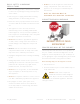
UNCR ATING B. IMPORTANT: Cut green polyband and remove styrofoam block before removing refrigerator from pallet. R E Q U I R E D TO O L S • Cutting utensil (utility knife) • Hammer C. Remove skid by carefully lifting the refrigerator off and place skid aside. • Crowbar • Phillips head screwdriver D. Open the unit and remove any packing material Styrofoam, tape, and any other material used for shipping purposes.
ELEC TRIC AL SPECIFIC ATIONS Do not, under any circumstances, cut or remove the third (ground) prong from the power cord. For personal safety, this appliance must be properly grounded. To minimize the depth of the cutout opening, the electrical outlet must be positioned as shown below. Outlet must be flush with wall. Rear wall of cut out 2" 2" 8" The unit should always be plugged into its own individual electrical circuit, which has a voltage rating that matches the rating plate.
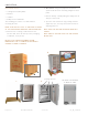
INS TALL ATION SPECIFIC ATIONS – S TAINLE SS SOLID & G L A SS D O OR True’s Stainless Solid and Glass Door units are designed to be inserted into a cabinet opening or free standing. Below are recommended dimensions for rough opening. TRUE’S CABINETS ARE UL R ATED FOR USE IN OUTDOOR SET TINGS. IN OUTDOOR LOCATIONS WHERE THE AMBIENT TEMPER ATURE REGUL ARLY E XCEEDS 95˚F, IT IS RECOMMENDED TO VENT THE RE AR OF THE CUT OUT OPENING IN THE ARE A SHOWN BELOW FOR OP TIMUM PERFORMANCE.
24 INCH ALL REFRIGERATOR TUR-24-R/L-SS-B TUR-24-R/L-SG-B FREEZER TUR-24D-SS-B TUF-24-R/L-SS-B TUF-24D-SS-B BEVERAGE CENTER WINE CABINET DUAL ZONE WINE CABINET TBC-24-R/L-SG-B TWC-24-R/L-SG-B TWC-24DZ-R/L-SG-B 25 3/4" 23 7/8" 23 7/8" 46 7/8" 34 1/4" 34 1/4" 25 1/4" 4 1/8" 3 3/4" DIMENSIONS MAY VARY BY ±1/ 8" TEC_TM_070 REV.
B e verage dispenser TUR-24BD-R/L-SS-B TUR-24DD-R/L-SS-B 24" SINGLE TAP UNIT ACCOMMODATES (1) SHORT 1/4 BARREL, (1) SLIM 1/4 BARREL, OR (1) 1/ 6 BARREL. 24" DUAL TAP UNIT ACCOMMODATES (2) 1/ 6 BARRELS OR (1) SLIM 1/4 BARREL AND (1) 1/ 6 BARREL. 25 3/4" 23 7/8" 11 7/8" 23 7/8" 10 1/4" 46 7/8" 50" 50" 25 1/4" 34 34 1/4" 1/4" 4 1/8" 3 3/4" DIMENSIONS MAY VARY BY ±1/ 8" Page 12 of 74 T RUE RE S ID E N TI A L ® 02/03/2021 TEC_TM_070 REV.
1 5 INCH ALL REFRIGERATOR TUR-15-R/L-SS-C WINE CABINET TUR-15-R/L-SG-C TWC-15-R/L-SG-C 25 3/4" 23 7/8" 14 7/8" 37 7/8" 34 1/4" 34 1/4" 16 1/4" 4 1/8" 3 3/4" DIMENSIONS MAY VARY BY ±1/ 8" TEC_TM_070 REV.
BEVERAGE DISPENSER TUR-15BD-R/L-SS-C 15" SINGLE TAP UNIT ACCOMMODATES (1) SLIM 1/4 BARREL OR (1) 1/ 6 BARREL. 25 3/4" 14 7/8" 23 7/8" 7 1/2" 10 1/4" 50" 37 7/8" 50" 34 1/4" 16 1/4" 34 1/4" 4 1/8" 3 3/4" DIMENSIONS MAY VARY BY ±1/ 8" Page 14 of 74 T RUE RE S ID E N TI A L ® 02/03/2021 TEC_TM_070 REV.
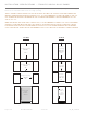
24 INCH INS TALL ATION SPECIFIC ATIONS – SOLID (OP) AND G L A SS FR A MED PANEL (OG) True’s 24 inch units with Solid and Glass Framed Panels are designed to be inserted into a cabinet opening or free standing. Below are recommended dimensions for rough opening. TRUE’S CABINETS ARE UL R ATED FOR USE IN OUTDOOR SET TINGS. IN OUTDOOR LOCATIONS WHERE THE AMBIENT TEMPER ATURE REGUL ARLY E XCEEDS 95˚F, IT IS RECOMMENDED TO VENT THE RE AR OF THE CUT OUT OPENING IN THE ARE A SHOWN BELOW FOR OP TIMUM PERFORMANCE.
24 INCH ALL REFRIGERATOR TUR-24-R/L-OP-B TUR-24-R/L-OG-B FREEZER TUR-24D-OP-B TUF-24D-OP-B WINE CABINET BEVERAGE CENTER TBC-24-R/L-OP-B TUF-24-R/L-OP-B TBC-24-R/L-OG-B TWC-24-R/L-OP-B TWC-24-R/L-OG-B BEVERAGE DISPENSER DUAL ZONE WINE CABINET TWC-24DZ-R/L-OP-B Page 16 of 74 TWC-24DZ-R/L-OG-B T RUE RE S ID E N TI A L ® TUR-24BD-R/L-OP-B 02/03/2021 TUR-24DD-R/L-OP-B TEC_TM_070 REV.
23 7/8" 3/4" 23 7/8" 23 1/8" 46 7/8" 34 1/4" 34 1/4" 25 1/4" 4 1/8" 3 3/4" 23 7/8" 23 7/8" 23 1/8" 42 5/8" 34 1/4" 34 1/4" 21" 4 1/8" 3 3/4" 23 7/8" 23 7/8" 11 7/8" 23 1/8" 10 1/4" 46 7/8" 50" 50" 25 1/4" 34 1/4" 34 1/4" 4 1/8" 3 3/4" 24" SINGLE TAP UNIT ACCOMMODATES (1) SHORT 1/4 BARREL, (1) SLIM 1/4 BARREL, OR (1) 1/ 6 BARREL. 24" DUAL TAP UNIT ACCOMMODATES (2) 1/ 6 BARRELS OR (1) SLIM 1/4 BARREL AND (1) 1/ 6 BARREL.
1 5 INCH INS TALL ATION SPECIFIC ATIONS – SOLID (OP) AND G L A SS FR A MED PANEL (OG) True’s 15 inch units with Solid and Glass Framed Panels are designed to be inserted into a cabinet opening or free standing. Below are recommended dimensions for rough opening. TRUE’S CABINETS ARE UL R ATED FOR USE IN OUTDOOR SET TINGS. IN OUTDOOR LOCATIONS WHERE THE AMBIENT TEMPER ATURE REGUL ARLY E XCEEDS 95˚F, IT IS RECOMMENDED TO VENT THE RE AR OF THE CUT OUT OPENING IN THE ARE A SHOWN BELOW FOR OP TIMUM PERFORMANCE.
1 5 INCH ALL REFRIGERATOR TUR-15-R/L-OP-C TUR-15-R/L-OG-C WINE CABINET TWC-15-R/L-OP-C TWC-15-R/L-OG-C BEVERAGE DISPENSER TUR-15BD-R/L-OP-C TEC_TM_070 REV.
14 7/8" 23 7/8" 37 7/8" 34 1/4" 34 1/4" 16 1/4" 4 1/8" 3 3/4" 23 7/8" 14 7/8" 23 1/8" 7 1/2" 50" 10 1/4" 37 7/8" 50" 34 1/4" 16 1/4" 34 1/4" 4 1/8" 3 3/4" 15" SINGLE TAP UNIT ACCOMMODATES (1) SLIM 1/4 BARREL OR (1) 1/ 6 BARREL. *INCLUDING 3 /4" THICK PANEL (PROVIDED BY OTHERS) DIMENSIONS MAY VARY BY ± 1/ 8" Page 20 of 74 T RUE RE S ID E N TI A L ® 02/03/2021 TEC_TM_070 REV.
CUS TOM PANEL INS TALL ATION – SOLID DO OR REFRIG ER ATOR / FREE ZER Overlay units can be fitted with custom panels to match adjacent cabinetry. Two specification options for panels sizes are given in these instructions for overlay units: Standard overlays and Integrated Panels. The standard overlay panel dimensions fully cover the provided appliance door. The integrated panel options extend above the door and conceal the hinge assembly to match full overlay cabinet doors. See pictures below for reference.
CUS TOM PANEL INS TALL ATION – SOLID DO OR REFRIG ER ATOR / FREE ZER S TANDARD OVERL AY PANEL 3/4" 23 5/8" 14 5/8" B A S O L ID D O O R 24 INCH 15 INCH DOOR PANEL WIDTH 235/8 " 145/8 " DOOR PANEL HEIGHT 29 23/32 " 2923/32 " DOOR PANEL DEPTH 3/4" max 3/4" max DOOR PANEL WEIGHT 20 lb. max 20 lb.
CUS TOM PANEL INS TALL ATION – G L A SS DO OR REFRIG ER ATOR S O L ID D O O R 3/4" 14 5/8" 23 5/8" S TANDARD OVERL AY PANEL B A 24 INCH 15 INCH DOOR PANEL WIDTH 235/8 " 145/8 " DOOR PANEL HEIGHT 29 23/32 " 2923/32 " DOOR PANEL DEPTH 3/4" max 3/4" max DOOR PANEL WEIGHT 10 lb. max 10 lb.
CUS TOM PANEL INS TALL ATION – DR AWER REFRIG ER ATOR / FREE ZER S TANDARD OVERL AY PANEL DRAWER PANEL WIDTH 235/8 " DRAWER PANEL HEIGHT 1411/16 " DRAWER PANEL DEPTH 3/4" max 235/8 " 235/8 " TOP DRAWER REFRIGERATOR TOP & BOTTOM DRAWER FREEZER 1411/16” 1411/16” SPEC SAME PANEL FOR TOP & BOTTOM FREEZER DRAWERS. FOR BOTTOM DRAWER ROTATE PANEL 180º.
SOLID (OP) AND G L A SS FR A MED PANEL (OG) INS TALL ATION R E Q U I R E D TO O L S 1 • Phillips Screwdriver • 3/8" Wrench • 1/8" Drill Bit • Ten (10) Screws #6 NOTE: THE LENGTH OF OVERL AY PANEL MOUNTING SCREWS NEED TO BE 3 /4" PLUS THE THICKNESS OF THE PANEL, MINUS 1/4". (3 /4"+ THICKNESS OF THE OVERL AY PANEL- 1/4" = LENGTH OF SCREW ). T YPES AND LENGTHS OF SCREWS CAN VARY DEPENDING ON THE MATERIAL USED See pages 21-22 for Overlay Panel Dimensions before installing.
6 6. Once all holes are pre drilled use the appropriate specified screws to secure the overlay panel onto the front of the refrigerator door. 7. Reinstall all components in reverse order. Door gasket snaps back into place. Overlay panel and door stay aligned with each other while installing.
DR AWER OVERL AY PANEL INS TALL ATION R E Q U I R E D TO O L S 1 • Phillips Screwdriver • 1/8" Drill Bit SEE PAGE 21 FOR OVERL AY PANEL DIMENSIONS BEFORE INSTALLING. FOR E ASY OVERL AY INSTALL ATION, DR AWER FRONT REMOVAL IS REQUIRED. PROCEDURE 1. Open the drawer and detach the front drawer panel by removing four #2 Phillips screws (two on each side). (See image 1). Save all these screws for later reinstallation. 2 2. Remove front drawer panel gasket. 3.
6 6. Secure overlay panel to drawer panel using appropriate size screws. 7. Reattach drawer gasket by pressing and snapping back into place in gasket channel. 8. Reattach drawer panel front to the drawer using four screws. Back of drawer 7 8 D R AW E R O V E R L AY PA N E L 24 IN CH Page 28 of 74 T RUE RE S ID E N TI A L ® 02/03/2021 TEC_TM_070 REV.
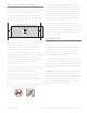
TAPPER UNIT INS TALL ATION UNDER COUNTER TOPS R E Q U I R E D TO O L S • 2" Diameter PVC pipe (12" long). Will need to be cut down to size when refrigeration unit is installed • Silicone Caulk When installing under counter tops use the dimensions in the diagrams for cutting into the counter top. Silicone caulk around the edge of the PVC pipe after it has been installed. Assemble drip tray and place it on top of unit as shown. 25/32 " 8" 12" 2" DIAMETER PVC PIPE TEC_TM_070 REV.
15 IN CH 7 7/16 " 211/16 " 6 3/32 " 815/16 " 10 9/32 " 5/32 " 2 3/8 "O.D. 211/16 " 13 5/8 " Drip tray 12 9/32 " 24 IN CH 11 31/32 " 211/16 " 10 5/8 " 9 3/8 " 10 23/32 " 5/32 " 2 3/8 "O.D. 211/16 " 13 3/4" Drip tray Page 30 of 74 T RUE RE S ID E N TI A L ® 1213/32 " 02/03/2021 TEC_TM_070 REV.
INS TALLING DR AF T S TANDARD AND HO OK UP R E Q U I R E D TO O L S • Phillips Head Screwdriver 1 • Adjustable Wrench 5 2 • 3/8" I.D. plastic tubing (3’) 4 • (2) Hose clamps K I T CO N T E N T S 1. CO 2 Tank (Shipped empty. Fill before use) 10 3 2. Draft Standard 7 3. Draft Standard Screws 9 4. Draft Head 5. CO 2 Pressure Regulator (single version/ double version) 8 6 6. Chill Hose 7. Rubber Washer 8. CO 2 Hose 9. Securing strap 10.
INS TALLING DR AF T S TANDARD AND HO OK UP (CONTINUED) 1. Place rubber washer over draft standard mounting holes. 2. Secure the draft standard to the cabinet with the screws provided. 1 3. Remove the draft cap and run the chill hose to the top of the draft standard. Hook the hose onto the stainless tube to keep hose from falling out (This hose will keep the draft standard cold). 4. Reinstall the draft cap. 5. Hook up the pressure regulator to the CO 2 tank.
INS TALLING DR AF T S TANDARD AND HO OK UP (CONTINUED) 7. Tighten the clamp down on the beer line hose. 7 8. Connect the CO 2 hose to the tapper. NO T E: TA P P ER D E SIGN VA R IE S BY A G E O F T HE C A BINE T. Older models (images 8 and 9) Connect the CO 2 hose to the tapper and tighten the clamp. Be sure the clamp is on the hose prior to connecting. Newer models (images 10 and 11) Remove the barbed fitting, and then thread the CO2 hose onto the tapper. 8 9. Install the beer tapper onto the keg.
PRE SSURE DISPENSING PRESSURES DIFFER ACCORDING TO: • The type of draft dispensing system • The length of draft dispensing line • The actual product – some require more, some require less False Head – Description: Large soap-like bubbles, head dissolves very quickly • Dry glasses • Improper pour • Pressure required does not correspond to beer temperature • The temperature of the product • Coils or direct draw beer lines warmer than beer in keg • The pressurizing agent: air pressure, CO 2 or special blen
CHANG ING CO 2 G A S CYLINDER FOLLOW THESE INSTRUCTIONS AT ALL TIMES WHEN YOU REPL ACE A CO 2 GAS CYLINDER: 1. Close cylinder at “A”. 2. Remove tap “D” from barrel. Pull pressure release ring on body of tap to release pressure remaining in line. (Do not close “C”). 3. Remove or loosen regulator key “B” by turning counter clockwise. 4. Remove regulator from used cylinder at “E”. 5.
CLE ANING INS TRUC TIONS FOR DR AF T TOWERS Draught dispensers, regardless of design, must be cleaned on a regular basis. Flushing your draught dispenser with water only is not enough. Cleaning is recommended whenever changing to a fresh keg. NOTE: USE CLE ANERS APPROVED BY YOUR BEER SUPPLIER AND FOLLOW THEIR INSTRUCTIONS. IF YOU ARE USING THE CLE ANING KIT PURCHASED FROM TRUE FOLLOW THESE INSTRUCTIONS: 11. F ill pump bottle with clean cool water and pump through lines until water runs clear.
I N S TA L L I N G T H E TO E K I C K L E V E L I N G R E F R I G E R ATO R A N T I -T I P B R A C K E T I N S T A L L A T I O N I N S TA L L I N G T H E 1 2 0 ° D O O R S TO P ( S TA N D A R D) I N S TA L L I N G T H E 9 0 ° D O O R S TO P (O P T I O N A L ) PRESERVE THE MOMENT® TEC_TM_070 REV.
INS TALLING THE TOE KICK 1. Remove from package that is taped to back of unit. 2. Line up and attach the toe kick to the bottom of the cabinet using the magnets. 5. The unit should be placed close enough to the electrical supply so that extension cords are never used. 6. Once installed in final location, insert toe kick by clipping in place. WARNING: COMPRESSOR WARR ANTIES ARE VOID IF THE UNIT IS MORE THAN 7 F T. (2.1M) FROM PLUG-IN CONNECTION OR IF AN E X TENSION CORD IS USED.
ANTI-TIP BR ACKE T INS TALL ATION IMP OR TA N T ! Anti-Tip Bracket (top view) ALL FREE STANDING DRAWER OR STACKED UNITS MUST HAVE ANTI-TIP BRACKETS INSTALLED. Back 27/32" K I T CO N T E N T S • 2 – Anti-Tip Brackets 22 3/16" • 4 – 3/16" x 2-1/4" Concrete Screws 18 1/2" • 4 – 12 x 2" Phillips Wood Screws R E Q U I R E D TO O L S • Floor Protector Front • Tape Measure • Marking Utensil FIG. 1. Top plan view of anti-tip bracket positioning.
ANTI-TIP BR ACKE T INS TALL ATION (CONTINUED) 5. With the appropriate provided hardware, install the anti-tip brackets. See fig. 2. NO T E: T HE C ONCR E T E S CR E W S A R E BL UE . 6. Carefully position the unit in its final installation location. Be sure the rear leveling legs slide into the anti-tip brackets. See fig. 3. NO T E: D O NO T L IF T T HE C A BINE T BY T HE C OUN T ER T OP S, D O O R S, D R AW ER S, O R G R IL L S.
INS TALLING THE 90 ° D OOR S TOP R E Q U I R E D TO O L S 1 • 3/8” Socket wrench • Phillips screwdriver K I T CO N T E N T S • 90º Hinge door stop • Door stop bracket PROCEDURE 2 1. Remove toe kick. 2. WARNING: Support the door while removing hinge. Door is heavy and weight will cause it to drop if not supported. Remove 2 3/8” bolts to detach 120º door hinge (standard). 3. Slowly remove door from unit by sliding down from top hinge. 3 4. Install door stop using screws already installed.
Page 42 of 74 T RUE RE S ID E N TI A L ® 02/03/2021 TEC_TM_070 REV.
T R U E P R EC I S I O N CO N T R O L® O P E R AT I O N A N D CABINET COMPONENTS (ALL MODELS) 24 I N C H R E F R I G E R ATO R & F R E E Z E R 24 INCH DUAL ZONE WINE C ABINE T 24 I N C H R E F R I G E R ATO R D R AW E R S 24 INCH FREEZER DR AWERS 1 5 I N C H R E F R I G E R ATO R HOME ALARM SYSTEM S H E LV I N G A D J U S T M E N T S TA C K I N G K I T I N S T R U C T I O N S PRESERVE THE MOMENT® TEC_TM_070 REV.
24 INCH REFRIG ER ATOR & FREEZER (FREE ZER NOT AVAIL AB LE IN G L A SS D O O R) = Power unit off / on cuts power to all relays = To display set point = = Press to change set point down Press to change set point up = To turn on accent light - This will leave light on all the time even when the door is closed = To switch color LED’s - 14 color TruLumina ® patent.
TRUE ALL REFRIGERATOR / FREEZER COMPONENTS TUR / TUF LOCATION OF SERIAL TAG ADJUSTABLE STAINLESS STEEL GLASS SHELVES (2) REMOVABLE KICK PLATE FOR EASY CLEANING DOOR LOCK TEC_TM_070 REV.
TRUE BEVERAGE CENTER COMPONENTS TBC LOCATION OF SERIAL TAG ADJUSTABLE STAINLESS STEEL GLASS SHELVES (2) SLIDE OUT WINE SHELF (1) FLOOR WINE CRADLE (1) REMOVABLE KICK PLATE FOR EASY CLEANING DOOR LOCK Page 46 of 74 T RUE RE S ID E N TI A L ® 02/03/2021 TEC_TM_070 REV.
TRUE WINE CABINET COMPONENTS TWC LOCATION OF SERIAL TAG ADJUSTABLE SLIDE OUT WINE SHELVES (5) FLOOR WINE CRADLE (1) REMOVABLE KICK PLATE FOR EASY CLEANING DOOR LOCK TEC_TM_070 REV.
TRUE BEVERAGE DISPENSER TUR-24BD DRAFT TOWER SPILL GRATE (TOP) DRIP PAN (BOTTOM) CHILL HOSE LOCATION OF SERIAL TAG SHELF (1) FOR USE WITH 1/4 SHORT KEG ONLY REMOVABLE KICK PLATE FOR EASY CLEANING DOOR LOCK Page 48 of 74 T RUE RE S ID E N TI A L ® 02/03/2021 TEC_TM_070 REV.
TRUE DUAL BEVERAGE DISPENSER TUR-24DD DOUBLE DRAFT TOWER SPILL GRATE (TOP) DRIP PAN (BOTTOM) CHILL HOSE LOCATION OF SERIAL TAG SHELF (1) FOR USE WITH 1/4 SHORT KEG ONLY REMOVABLE KICK PLATE FOR EASY CLEANING DOOR LOCK TEC_TM_070 REV.
24 INCH DUAL ZONE USER INTERFACE COMM ANDS = Power, cuts power to all relays, resumes pulldown = To display set point = Press to change set point down, hold to scroll down Press to change set point up, hold to scroll up = = = To turn on Accent Light - This will leave light on all the time even when the door is closed To turn on door ajar alarm & high temperature alarm - Door ajar alarm activates after 7 minutes.
TRUE WINE CABINET - DUAL ZONE COMPONENTS TWC-DZ LOCATION OF SERIAL TAG FULLY ADJUSTABLE WINE SHELF (1) NON-ADJUSTABLE SHELF (1) FULLY ADJUSTABLE WINE SHELVES (3) REMOVABLE WINE CRADLE (1) REMOVABLE KICK PLATE FOR EASY CLEANING HOME SECURITY TIE IN TEC_TM_070 REV.
24 INCH REFRIG ER ATOR / FREEZER DR AWERS = Power unit off / on cuts power to all relays = To display set point = = Press to change set point down Press to change set point up = To turn on accent light - This will leave light on all the time even when the door is closed = To switch color LED’s - 14 color TruLumina ® patent. To turn on door ajar alarm & high temperature alarm - Door ajar alarm activates after 7 minutes.
TRUE REFRIGERATED DRAWERS TUR-24D TWO HEAVY DUTY LEXAN ORGANIZERS PER DRAWER EXCLUSIVE TRUE®-GLIDE SOFT-CLOSE FEATURE FOR BOTH DRAWERS REMOVABLE KICK PLATE FOR EASY CLEANING TEC_TM_070 REV.
TRUE FREEZER DRAWERS TUF-24D EXCLUSIVE TRUE®-GLIDE SOFT-CLOSE FEATURE FOR BOTH DRAWERS REMOVABLE KICK PLATE FOR EASY CLEANING Page 54 of 74 T RUE RE S ID E N TI A L ® 02/03/2021 TEC_TM_070 REV.
1 5 INCH USER INTERFACE COMM ANDS Control is located behind the user interface and can be accessed by removing 3 Phillips screws. This will also give you access to the user interface, and LED driver.
TRUE BEVERAGE DISPENSER TUR-15BD DRAFT TOWER SPILL GRATE (TOP) DRILL PAN (BOTTOM) LOCATION OF SERIAL TAG CHILL HOSE REMOVABLE KICK PLATE FOR EASY CLEANING DOOR LOCK Page 56 of 74 T RUE RE S ID E N TI A L ® 02/03/2021 TEC_TM_070 REV.
TRUE ALL REFRIGERATOR COMPONENTS TUR LOCATION OF SERIAL TAG ADJUSTABLE SPILL PROOF GLASS SHELVES (2) DOOR LOCK REMOVABLE KICK PLATE FOR EASY CLEANING TEC_TM_070 REV.
TRUE WINE CABINET COMPONENTS TWC LOCATION OF SERIAL TAG ADJUSTABLE SLIDE OUT WINE SHELVES (5) FLOOR WINE CRADLE (1) DOOR LOCK REMOVABLE KICK PLATE FOR EASY CLEANING Page 58 of 74 T RUE RE S ID E N TI A L ® 02/03/2021 TEC_TM_070 REV.
HOME AL ARM S YS TEM – DUAL ZONE WINE C ABINE T ONLY Dual Zone wine units are provided with three wires located behind the kick-plate that may be connected to a home alarm system. These connections are for low voltage, low current circuits similar to those used as signals for alarms on doors and windows. Refer to the specifications of your alarm system to determine the type of circuit used.
WINE SHELVING AD JUS TMENT G L A SS SHELVING AD JUS TMENT The glide out wine shelves in TBC, TWC and TWZ-DZ models consist of 3 pieces. These pieces are the wire wine rack and 2 mounting bracket/glide assemblies (one for the hinge side and one for the non-hinge side). The glide out glass shelves are already attached to the mounting bracket/glide assemblies. To remove the wine shelf, pull up on the front of the wine rack and it will separate from the two mounting brackets.
INS TALL ATION SPECIFIC ATIONS - S TACKED UNIT S (SOLID AND G L A SS D OOR AND OVERL AY PANEL S) True’s stacked units are designed to be inserted into a cabinet opening or free standing. Below are recommended dimensions for rough opening. 24 IN CH 15 IN CH Rough Opening HEIGHT 691/2 " Rough Opening HEIGHT 691/2 " Rough Opening WIDTH 24" Rough Opening WIDTH 15" Rough Opening DEPTH 24" Rough Opening DEPTH 24" TEC_TM_070 REV.
TRUE S TACKING KIT R E Q U I R E D TO O L S • 1/4 inch socket and ratchet • Level • Floor protector K I T CO N T E N T S • (1) Louver Grill • (2) Stacking Brackets • (4) 1/4” Hex Head Screws 1 STACKING BRACKETS PROCEDURE 1. Lay floor protectant down. 2. Uncrate cabinets and secure both shelving and doors/drawers. 3. Install the anti-tip device per its instructions. (Page 16). 4. Trial fit anti tip brackets using the lower cabinet. 2 5. Carefully lift the top cabinet and place on the lower cabinet.
TRUE S TACKING KIT (CONTINUED) 4 10. Install the new louver grill on top cabinet. NOTE: MAK E SURE ANY PL ASTIC PROTECTIVE MATERIAL IS REMOVED FROM LOUVER GRILL BEFORE INSTALLING. 11. D oor must be open for installation. Slide louver grill into place and snap both sides into the unit. See image 4. 12. Installation is complete. 24 INCH TEC_TM_070 REV.
TRUE S TACKING KIT FOR UNIT S WITH OVERL AY PANEL S R E Q U I R E D TO O L S • 1/4 inch socket and ratchet • Level • Floor protector K I T CO N T E N T S • (2) Stacking Brackets • (4) 1/4" Hex Head Screws 1 PROCEDURE 1. Lay floor protectant down. STACKING BRACKETS 2. Uncrate cabinets and secure both shelving and doors/drawers. 3. Install the anti-tip device per its instructions. (Page 16). 4. Trial fit anti tip brackets using the lower cabinet. 5.
PLE ASE NOTE WHEN ADDING A PANEL TO THE GRILL OR DOOR, AIR FLOW NEEDS TO BE TAK EN INTO CONSIDER ATION. SEE IMAGES 3 AND 4 . IM A G E 3 Air Flow Out IM A G E 4 Air Flow In 3 7/16 " Approximate distance from bottom of door to bottom of cabinet. 24 INCH TEC_TM_070 REV.
CUS TOM WO OD LOU VER TEMPL ATE 15 IN CH 14 3/4" 9" 2 " 7/8 25/32 Detail A 3 5/8 " Detail B 11/32 " " 11/32 " 1/2" (3 PLCS.) R1/4" (6 PLCS.) 24 IN CH 23 3/4" 18" 2 " 7/8 25/32 Detail A 3 5/8 Detail B " 11/32 " 11/32 " 1/2" (3 PLCS.) R1/4" (6 PLCS.
S TA I N L E S S S T E E L EQ U I P M E N T C A R E A N D C L E A N I N G GENERAL MAINTENANCE CO N D E N S AT I O N S E R V I C E I N F O R M AT I O N F R E Q U E N T LY A S K E D Q U E S T I O N S WARR ANT Y PRESERVE THE MOMENT® TEC_TM_070 REV.
S TAINLE SS S TEEL EQUIPMENT C ARE AND CLE ANING CAUTION: DO NOT USE ANY STEEL WOOL, ABR ASIVE OR CHLORINE BASED PRODUCTS TO CLE AN STAINLESS STEEL SURFACES. S TAINLE SS S TEEL CLE ANING AND RE S TOR ATION S TAINLE SS S TEEL OPP ONENT S There are three basic things which can break down your stainless steel’s passivity layer and allow corrosion to rear its ugly head. 1. Scratches from wire brushes, scrapers, and steel pads are just a few examples of items that can be abrasive to stainless steel’s surface.
S TAINLE SS S TEEL EQUIPMENT C ARE AND CLE ANING 8 TIP S TO HELP PRE VENT RUS T ON S TAINLE SS S TEEL 1. Maintain the Cleanliness of Your Equipment – Avoid build-up of hard stains by cleaning frequently. Use cleaners at the recommended strength (alkaline chlorinated or non-chloride). 2. Use the Correct Cleaning Tools – Use non-abrasive tools when cleaning your stainless steel products. The stainless steel’s passive layer will not be harmed by soft cloths and plastic scouring pads. 3.
G ENER AL M AINTENANCE FREQUENTLY A SKED QUE S TIONS Keeping the condenser coil clean will minimize required service and lower electrical cost. The condenser coil is accessible from the front. The condenser coil should be cleaned by removing dust and other build-up from the tube assembly with vacuum or a cleaning rag. When properly cleaned you should be able to see through the tube assembly. Warranty does not cover cleaning he condenser coil. Q. How do I adjust the temperature? A.
Q. How much distance is needed from the wall to have the hinge on the wall side and still open 90 degrees? A. 2 inches Q. Why doesn’t the warranty cover commercial units in my home? A. Due to Department of Energy regulations on refrigerator energy use, we are not able to market and sell our commercial units in homes. Providing a warranty to home users is included in this. Q. What is the Decibel rating of the units? A. 42-47 db. 1 " 7/8 Q. How do I change the lighting? A.
PLE ASE NOTE: THE GASK ETS DO NOT PROVIDE A WATER TIGHT SE AL, SO IT IS RECOMMENDED THAT THE UNIT IS INSTALLED SO THAT THE COUNTERTOP OF YOUR OUTDOOR KITCHEN COVERS THE DOOR OR DR AWER GASK ET. Q. What should I do in the winter? Do I have to bring it in? How cold can it get before it’s a problem? A. In regions with cold winters (consistently below 32ºF), True refrigerators should be turned to off, and emptied of all contents. If exposed to the elements, covering your cooler will extend its life and beauty.
T R U E R E S I D E N T I A L® S E R I E S L I M I T E D WA R R A N T Y S TAT E M E N T LIMITED 30 DAY COSMETIC WARRANT Y Stainless steel doors, handles, and shelves are warranted to be free from defective materials or workmanship for a period of thirty (30) days from the date of original retail purchase. Any defects must be reported to the selling dealer within thirty (30) days from the date of original retail purchase. This limited warranty excludes any type of freight / concealed damage.
CONTACT US true-residential.com | t o ll f r e e 8 8 8 .616. 878 3 BP_162314_12.20 636.240.2400 T RUE RE S ID E N TI A L ® 02/03/2021 TEC_TM_070 REV.