
Operation Manual

6
Position drive rollers such that they are in front of or behind the
tyres at wheel hub height (middle of wheel). No height com-
pensation is required for the standard installation (frame height
approx.185 mm).
With frame heights of 140 mm to 185 mm, use U-bolt exten-
sion kit (Part no. 60010-00100) and spacer plate set (Part no.
60010-65000) to set the drive rollers to the correct height
(middle of wheel).
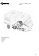
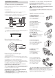
For height compensation (as shown in fig. B) clamp 1 to 3
spacer plates (d) between the cross strut and the vehicle
frame (maximum of 3 plates). Use the extended U-bolts for
installation.
For greater height differences, a low chassis kit (Part no.
60010-09400) is available from Truma as a special accessory
– for installation see instructions provided with low chassis kit.
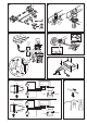
4. Fig. C: Create an adequate distance between the chain gu-
ard and the wheels/shock absorbers by moving the drive units
to the side so that they do not come into contact with each
other.
5. Fig. D: Move adjustable middle tube into a central position
and tighten the 2 bolts at the side a little.
Create the correct distance between the tyre and the roller
(20 mm) with the provided spacer by moving the drive units in
the longitudinal direction.
6. Once the drive units have been correctly positioned, tigh-
ten the U-bolt nuts a little and then check that the distance
between the rollers and the tyres is 20 mm. The weight of the
caravan must be on the wheels when doing this. Check that
there is adequate floor clearance.
7. Re-check the distance of 20 mm from the tyres (with weight
on wheels) and then tighten the nuts on the U-bolts (20 Nm for
W/F 13 mm), and the 4 bolts of the middle tube (15 Nm).
8. Fig. B: After installing in the correct position, fit stoppers
(C) immediately in front of and behind the retaining plates. The
stoppers prevent the Mover from sliding on the vehicle frame
during operation.
When the rollers are applied the minimum distance for
dimensions „a” and „b” is 10 mm (fig. C).
9. Once the Mover has been correctly fitted and secured, the
one-sided operating facility that is available as a special acces-
sory can be installed as described in the provided installation
instructions.
Installation of motor cables and control unit
Remove battery cable terminals and disconnect any ex-
ternal electrical power before starting work. If you are
unsure about the electrical installation, have it checked out by
a qualified Auto Electrician.
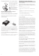
Pre-fitted, each motor has two heavy-duty cables (6 mm²). All
the cables have to be routed along the underside of the cara-
van floor to the point where the electronic control unit will be
situated. An example of a suitable location for the relay cont-
roller is in a bed stowage box in close proximity to the mano-
euvring aid, at least 40 cm away from the battery.
Approval
When installing the Mover always observe the technical and
administrative rules and regulations of the country in which the
vehicle is to be registered for the first time.
Any modification to the unit, or the use of spare parts and
functionally-important accessories which are not original
Truma components, or failure to respect the installation and
operating instructions, will lead to the cancellation of the gua-
rantee and to exclusion of claims for liability. in addition to this,
the operational approval for the device will be cancelled.
For Germany, a general operating permit (ABE) has been
issued. For export requirements please contact service.
Tools and facilities required
To install the unit you will need:
13 mm AF socket / wrench 13 mm AF combination spanner
Torque wrench (automotive size)
Cable cutter/Crimping tool
Power drill / screwdrivers / 25 mm hole cutter
Portable 2 tonne trolley jack and axle stands to suit
Appropriate lighting
Choice of location
We recommend to fit the Mover behind the rear axle. Under
special circumstances (for example lack of space) the Mover
can also be fitted in front of the front axle. Only the provided
U-bolts must be used to attach the Mover (or the U-bolt
extension special accessory).
The frame of the vehicle must be kept free of rust and heavy
soiling and without any damages to the suspension components.
The caravan must be fitted with the same size and type of tyre
on each wheel; to ensure the wheel diameter is identical, we
recommend to install and set up the mover only with new
tyres, these are to be inflated to manufacturer’s specifications.
The Caravan Mover weighs approximately 30 kg. Ensure
the pay load allowance of the caravan can accommodate this.
Installation of the drive units
The AL-KO Vario III / AV installation kit (Part no. 60010-
21500) must be used for caravans with the AL-KO Vario-III /
AV chassis (frame thickness less than 2.8 mm). For installation
see instructions provided with installation kit.
1. Fig. A: Remove all components from packing and place on
the floor.
2. Loosely screw all components together to form a cross
strut. Nuts must be no more than finger-tight.
3. Fig. B: Place the assembly loosely to the chassis with the
exception of the stoppers (C – stoppers are attached when
installation is complete).
For chassis with U-profile frame, use U-profile chassis kit
(Part no. 60010-09200) instead of clamping plates provi-
ded for standard installation. Fit the two clamping plates to the
frame as shown in the illustration and attach using the
U-bolts and nuts provided in the installation kit. (The provided
stoppers replace the standard stoppers (C) and are attached
when installation is complete).