
Operation Manual

7
The battery connection cables may not be lengthened.
The connecting cables to the motor and the battery must
be separate and must not be routed via the relay box.
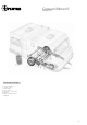
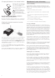
1. Fig. F: Attach relay controller (installed horizontally with
antenna in a vertical position) to floor of stowage box with
provided screws.
2. Drill a 25 mm hole, approximately 150 mm in front of control
unit for the motor cables.
Take care to avoid any chassis members, gas pipes and
electrical wires)! The connecting cables to the motor
and the battery must not be routed parallel to each other.
3. Route motor connecting cable to relay controller along un-
derbody of caravan and attach to chassis or underbody using
the provided clips and screws. Take care to secure the cables
so they will not chafe on the chassis or sag below the floor
(use supplied protection tubing).
The motors move when the drive rollers are engaged,
so allow a little slack at the motors to avoid the cables
being stretched.
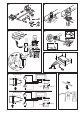
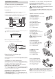
4. Mark the relevant motor connecting cables and then cut to
length accordingly (before or after the axle, depending on the
installation). Crimp provided spade connectors to the cables
(fig. G) and connect in accordance with wiring diagram
(fig. E) (red = positive, black = negative).
Excess cable must be cut to length and not looped inside
the bedding locker. A good quality connection on each
cable is essential!
5. Fig. E and F: Route battery connecting cables (10 mm²) to
relay controller and securely attach using the provided clips
and screws.
Route battery connecting cables so that they do not chafe
(particularly at leadthroughs through metal panels). Use
water hoses or leadthrough grommets to prevent damage to
cables. Connect battery connecting cables to the existing
battery terminals (red = positive, black = negative).
6. Re-check whether all cables are correctly connected,
attached using the provided clips and cannot chafe.
Commissioning the Mover
1. Ensure the battery used to operate the Mover is fully char-
ged (do not operate the Mover if the voltage in the battery is
below 10.2 V DC).
2. Place the caravan outside in a clear area and pull on the
handbrake. Ensure that the rollers are disengaged from the
road tyres and the corner steadies are raised.
3. Connect battery terminals to battery, check that all cables
are secure and not hot or indicating signs of short circuits, etc.
4. Press the red button on the remote control twice within one
second. This switches the remote control on and the LED illu-
minates. If LED does not illuminate, check polarity and conditi-
on of batteries in remote control. The remote control switches
itself off after about 40 seconds if no buttons are pressed.
5. Check that both drive motors are stationary. With the hand-
set switched on, and within 2 m of the control unit, press the
forward button. Check that both drive motors are driven.
6. Press the red button again to switch off the handset and
Mover.
7. Engage the drive rollers by use of the 19 mm AF wrench
provided or the steady leg brace. The action will be quite stiff
and will snap into place. The movement required is just over
1/2 turn. Turn the wrench until it will turn no more without
excessive force. do this on both sides of the caravan.
8. Ensure that there no obstacles around the caravan, release
the handbrake and switch the remote control on. Now check
all functions several times according the operating instructions.
9. Press the red button again to switch the handset and Mover off.
Release the drive mechanisms with the wheel brace (19 mm)
and recheck the roller to tyre spacing. Adjust if necessary.
The distance between the rollers and the tyres is 20 mm.
Warning information
The yellow sticker with the warning information, which is en-
closed with the appliance, must be affixed by the installer or
vehicle owner to a place in the vehicle where it is clearly visible
to all users (e.g. on the wardrobe door)! Ask Truma to send you
a sticker, if necessary.
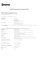
Technical data
Designation: Caravan Mover II
Area of operation: Single axle caravans with a
total weight up to 1700 kg
Operational voltage: 12 V DC
Current consumption: Average 30 A
Maximum 120 A
Stand by consumption: < 15 mA
Speed: Approx. 22 cm per second
(depending of the tyre size)
Maximum tyre width: 205 mm
Weight: Caravan Mover II, approx. 30 kg
Right to effect technical modifications reserved!