
Product Manual

9
The device must only be installed
and repaired by an expert. Read the
installation instructions carefully before
commencing the work, and then com-
ply with them!
Scope of delivery
– 1 Saphir comfort RC AU
– 1 Remote control with batteries
– 1 IR receiver
– 4 Fastening brackets with screws, 1 clamping strap
– 2 Condensation traps
– 2 Floor grilles
– 1 Installation template
– 1 set of operating instructions / installation instructions
Intended use
This device has been designed for installation in motor homes
and caravans and is intended for use in the private sector.
Regulations
Guarantee claims, warranty claims and acceptance of liability
will be ruled out in the event of the following:
– Modifications to the device (including accessories)
– Failure to use original Truma parts as replacement parts and
accessories
– Failure to follow the installation and operating instructions
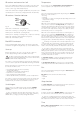
Selecting a location
The device must always be installed so that it is easy to ac-
cess at all times for service work, and also easy to remove
and install.
In the event of restricted installation space being avail-
able, the 2 connector cables (power and IR receiver ca-
ble) must be of sufficient length for the device to be pulled out
with the cables attached and the cover to be opened.
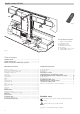
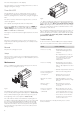
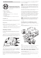
20 mm
30 mm
20 mm
290 mm
440 mm
200 mm
628 mm
Fig. 12
In order to achieve homogeneous vehicle cooling, the air
conditioning system must be installed in a central loca-
tion in a stowage box or the like so that the cold air is evenly
distributed in the caravan or motor home.
The air conditioning system is attached to the floor, which
must be level and smooth. The air inlet (LE), the air outlet (LA)
and the connections (11) may need to be fitted with additional
gaskets if the system is attached to a channelled floor, for
example.
Installation instructions
The room air that is going to be cooled is drawn in again from
the vehicle interior by the device via openings with a total
area of at least 300 cm².
The circulated air is cleaned and dried during the opera-
tion of the device. For this reason, suitable measures
must be taken to ensure that the air to be cooled is drawn out
of the vehicle interior if the equipment is installed in external
stowage spaces (e.g. false floor). Drawing in air from the out-
side can have a detrimental effect on the effectiveness of the
air conditioning system.
If possible, position the device so that the frame of the vehicle
is between the air inlet (LE) and the air outlet (LA).
Insert the installation template into the stowage box in which
the equipment is being installed and check the amount of
space available for floor apertures. The air conditioning sys-
tem should have at least 20 mm of clearance at the sides and
30 mm at the rear from walls and furniture items in order to
prevent noise transmission during operation. The minimum
clearance at the front is 200 mm, so that the fluff / particle
filter can be changed.
The openings in the floor of the vehicle must be freely
accessible, and must not be blocked by frame sections
or the like behind them! The openings must not be within
range of the wheel spray. A splash guard must be fitted if
necessary.
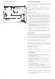
Installing the air conditioning system
Place installation template in stowage compartment and fix in
position.
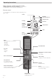
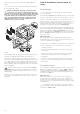
Mark the mounting holes for the 2 brackets (2 – HW) and the
2 side fastening brackets (3).
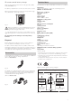
3
5
KO
LA
Ø 50 mm
11
1
2
2
3
LE
Fig. 13
Mark floor opening “LE” for the supply air intake, “LA” for the
supply air outlet and “KO” for the condensation drains.
Remove template and cut out the marked floor openings.
Before drilling, always check for underlying / concealed
cables, gas lines, frame sections and the like!
Then seal the edges of the openings in the floor of the vehicle
with underbody protection.
Screw on the 2 side fastening brackets (3) with 2 screws each
and the 2 brackets (2 – HW – leg must be pointing towards
the outside!) with 3 screws each.