
Operation Manual

15
Trumatic E 2400
Symbols used
Symbol indicates a possible hazard.
Comment including information and tips.
Safety instructions
The use of upright gas cylinders from which gas is taken in
the gas phase is mandatory for the operation of gas regula-
tors, gas equipment and gas systems. Gas cylinders from
which gas is taken in the liquid phase (e.g. for fork lifts) must
not be used, since they would result in damage to the gas
system.
If the gas system is leaking or if there is a smell of gas:
extinguish all naked flames
do not smoke
switch off the appliances
shut off the gas cylinder
open windows and door
do not actuate any electrical switches
have the entire system checked by an expert!
Repairs may only be carried out by an expert!
A new O-ring must always be installed after dismantling the
exhaust duct!
Guarantee claims, warranty claims and acceptance of liability
will be ruled out in the event of the following:
modifications to the unit (including accessories),
modifications to the exhaust duct and the cowl,
failure to use original Truma parts as replacement parts and
accessories,
failure to follow the installation and operating instructions.
It also becomes illegal to use the appliance, and in some
countries this even makes it illegal to use the vehicle.
The gas supply’s operating pressure (30 mbar) must be the
same as the unit’s operating pressure (see type plate).
Liquid gas systems must comply with the technical and
administrative regulations of the respective country of use
(e.g. EN 1949 for vehicles or EN ISO 10239 for boats in
Europe). National directives and regulations (e.g. DVGW
worksheet G 607 for vehicles and G 608 for boats in Germany)
must be complied with.
For vehicles for commercial use, the relevant accident preven-
tion regulations issued by the professional associations are to
be respected (BGV D 34).
The inspection of the gas system is to be repeated every
two years by an approved liquid gas specialist (DVFG, TÜV,
DEKRA). This is to be confirmed on the corresponding inspec-
tion certificate (G 607, G 608, or BGG 935).
The vehicle owner is always responsible for arranging the
inspection.
Pressure regulating equipment and hoses must be replaced
with new ones no more than 10 years after the date of
manufacture (every 8 years if used commercially). This is the
responsibility of the operator.
Liquid gas equipment must not be used when refuelling, in
multi-storey car parks, in garages or on ferries.
–
–
–
–
–
–
–
–
–
–
–
Table of contents
Symbols used ...................................................................... 15
Safety instructions .......................................................... 15
Important operating notes ............................................. 16
Operating instructions
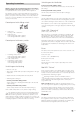
Control panel with sliding switch ....................................... 17
Control panel with rotary switch ......................................... 17
Switching on the Heating ................................................... 17
Switching on the Ventilation ............................................... 17
Switching off ....................................................................... 17
Green LED “Operating” ...................................................... 17
Fuses ................................................................................... 17
Red LED “Failure” ............................................................... 17
Disposal ............................................................................. 17
Accessories ....................................................................... 18
Technical data ................................................................... 18
Trouble-shooting list ........................................................ 19
Declaration of conformity .............................................. 20
Manufacturer’s terms of warranty ................................ 20
Installation instructions
Intended use ........................................................................ 21
Approval .............................................................................. 21
Regulations .......................................................................... 21
Notes on the installation in commercial vehicles .............. 21
Notes on installation in driver's cab .................................... 21
Notes on installation in boats .............................................. 21
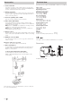
Choice of location ............................................................ 21
Exhaust duct ..................................................................... 22
Permissible duct lengths ..................................................... 22
Interior installation using the wall cowl kit ............... 22
Assembly of wall cowl ........................................................ 22
Fastening the appliance ...................................................... 22
Double cowl duct connection to the heating
appliance ........................................................................... 23
Under-floor assembly with wall cowl kit ..................... 23
Fastening the appliance ...................................................... 23
Warm air distribution and circulating air return with
interior installation ........................................................... 23
Warm air distribution .......................................................... 23
Circulating air return ............................................................ 23
Warm air supply and circulating air return with
outside assembly ............................................................. 23
Connection of the ducts to the appliance ........................... 24
Assembly of the ducts at leadthroughs .............................. 24
Warm air distribution .......................................................... 24
Circulating air return ............................................................ 24
Fitting the control panel ................................................. 24
Installing the control panel with rotary switch ................... 24
Installing the control panel with slide switch ..................... 25
Fitting the electronic control unit ................................. 25
Electrical connection 12 V / 24 V .................................. 25
Gas connection ................................................................. 25
Function check ................................................................. 25
Warning information ....................................................... 25