
Operation Manual

24
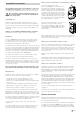
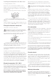
Connection of the ducts to the appliance
Remove the two protective gratings from the appliance. Coat
the two pipe pieces LF 18 (1) and the rein-forced ends (2) with
plastic body sealant and insert in the opening of the appliance
(W + U). Secure with two self-tapping screws (3). The duct
connection must be correctly assembled, otherwise splash
water can enter the appliance!
Assembly of the ducts at leadthroughs
Drill two openings 73 mm diameter (W + U). Coat the connec-
tion fittings (4) on the flange with plastic body sealant and screw
on, at opening (U) place the protective grating (5) in between.
Cut the two duct pieces LF 18 (6) to the required length, if
necessary, coat on the inside with plastic body sealant and slide
onto the connection (4). Secure with worm drive hose clip (7).
On the inside, screw on the connection fitting (8) over the
opening (W – can also be screwed together with the connec-
tion fitting on the out-side). With hollow double walls make
sure to seal the intermediate space.
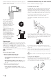
Warm air distribution
Connect duct VR 80 (9) 80 mm diameter and secure with self-
tapping screw (10). The various parts for the duct branching
can also be mounted on the connection fitting (8), for the fur-
ther routing of the ducts VR 72 (72 mm diameter), ÜR (65 mm
diameter) or ZR 18 (49 mm diameter).
In order to prevent overheating, at least one air passage must
always be kept open (swivel nozzle SCW 2). Secure all duct
connections with self-tapping screws. Fasten duct with clamp.
The hot air system is individually designed for each vehicle
model using a modular principle. A wide range of accessories
is available for this purpose (see brochure). Diagrams with op-
timum installation suggestions for hot air systems in all of the
most popular motor home models can be requested free of
charge via the Truma service centre.
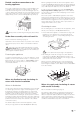
Circulating air return
The appliance must be able to intake sufficient circulating
air through the opening (U). If the circulating air return takes
place inside a storage compartment, drill two holes (13) into it,
each measuring 75 mm in diameter or apply an appropriately
sized opening.
Do not obstruct air passages to the appliance!
If the storage compartment is to remain in full use, the return
air can be drawn in through a swivel nozzle SCW 2 and a duct
piece VR 80. For this purpose screw a connection fitting over
the opening (U). Overall length up to the appliance max. 2 m!
Fitting the control panel
When using control panels which are specific to the
vehicle or manufacturer, the electrical connection must
be effected in accordance with Truma interface specifications.
Any modification made to the Truma components pertaining
to this will lead to the cancellation of the guarantee and to the
exclusion of any claims for liability. The installer (manufacturer)
is responsible for providing operating instructions for the user
as well as for the labelling of the control panels!
When selecting the location, take note that the control panels
must not be subjected to any direct radiant heat. Length of
the connection cable 4 m or 10 m.
If installation is only possible behind curtains or in similar
locations with temperature fluctuations, a remote sensor for
the ambient temperature must be used (Accessories).
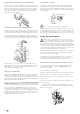
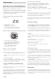
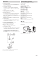
Installing the control panel with rotary switch
If flush mounting is not possible, Truma will supply an
on-surface frame (1 – part no. 40000-52600) as an
accessory on request.
Drill a hole Ø 55 mm in diameter.
Plug the control panel cable (2) into the control panel (3) and
then fit the rear cover cap (4) as a stress-relieving device.
Push the cable through to the rear and lay it to the electronic
control unit.
Secure the control panel with four screws (5) and fit the cover
frame (6) in place.
Truma offers side parts (7) in eight different colors for
finishing the cover frames (6) in a visually pleasing way.
Please ask your dealer.
Ø 55 mm
2
7
7
6
1
3
5
4