While in flight 1: Beginners should obtain safety and technical guidance from an experienced individual, since learning alone to operate this machine is potentially dangerous. 2: Choose a safe flying area that is free of obstruction and people. 3: Do not fly in a potentially dangerous environment. 4: Do not operate while standing on tilted ground to avoid loss of balance. 5: Do not insert hands and objects in rotating parts.
After-flight safety inspection 1: Immediately inspect parts after every flight. Be sure to replace, retighten any missing or loose screws and replace any damaged parts. 2. Wipe down grease, oil, dirt and dust with a clean cloth. 3. If the unit is to be stored out of operation for a long period of time, completely drain remaining fuel from the fuel tank and carburetor. 4: Store the unit in an area free of direct sunlight, or other areas that may result in rise in temperature (e.g., car).
Preassembly precautions 1. Before assembly, read the instruction manual thoroughly and familiarize yourself with the unit's structure and assembly procedures. Failure to assemble the unit properly may not only impair performance but also increases the risk of danger. 2. Before assembly, check description and quantity of parts. In the event of missing or defective items, contact retailer of original purchase where authorized distributor or TSA support department can be located.
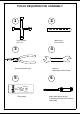
TOOLS REQUIRED FOR ASSEMBLY 8 1 2 7 5.5 12 Metric ruler (Over 30cm) Cross wrench (5.5~12) 3 4 Universal ball link plier Spanner (6mm/8mm/12mm/21mm) 5 6 +15 +10 +5 0 -5 -10 -15 (Allen head) Screw drivers (1.5mm/2mm/2.5mm/3mm/3.
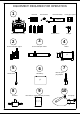
EQUIPMENT REQUIRED FOR OPERATION 1 Receiver On/off switch Receiver battery 3 Axis gyro system 4.8 V 1800 mA PWOER Transmitter(7 channels) 2 50 size helicopter engine Rudder servo Servos 3 Charger 4 50 size helicopter muffler Starter 12V 5 Starter shaft 6 12V Battery 7 Remote glow plug adapter 12V 1.
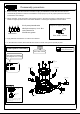
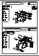
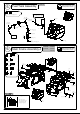
1 T-001-03 Main Frame Assembly-1 T-007-02 Lo ck T-003-00 Please apply loctite when locking all metal screws . T-005-01 M2-4 Bind screw Insert M2-4 retaining blind screws after installing the bearing 37.5mm Canopy rear support 1 30.5mm Canopy front support 1 37.5mm Canopy rear support M3-6 Bind screw M3-8 Cap screw 2 M2-4 Bind Screw M3-6 Cap screw Custom Washer M3-6 Bind screw M3-6 Bind screw 4 M3-6 Cap screw 2 Main shaft bearing block 30.
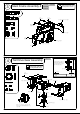
3 T-001-02 Main Frame Assembly-3 37.5mm Canopy rear support T-022-02 Lo ck Please apply loctite when locking all metal screws . T-003-00 T-005-01 1 M3-6 Cap screw 30.5mm Canopy front support 1 23mm Servo support 2 M3-6 Cap screw 4 M3-6 Cap screw 37.5mm Canopy rear support Ø5xØ10x4 Flange Brg 23mm Servo support Ø5xØ10x4 Flange Brg 1 M3-6 Cap screw Fuel tank damper 30.5mm Canopy front support Left frame 4 Tail Drive Gear Assembly Lo ck T-019-00 7.
Fuel Tank Assembly 5 M3-5 Stainless steel bind screw 1 T-003-00 Lo ck Please apply loctite when locking all metal screws . To muffler pressure nipple Fuel tube Ø2.5xØ4x90L Hex nut Fuel tube Ø2.5xØ5.5 Fuel tube Ø2.5xØ5.
7 Main Frame Assembly-5 M4-5 SS 1 M3-6 Bind screw 5 M3-8 Cap screw 6 Custom washer 6 Ø6xØ15x5 Brg 1 Ø10xØ19x5 Brg 2 M3-8 Cap screw Custom Washer T-002-02 T-010-00 T-006-01 T-016-01 Lo ck Please apply loctite when locking all metal screws .
Lo RPM Sensor Assembly 8 ck Please apply loctite when locking all metal screws . Two means of induced magnet RPM Sensor assembly are provided! N pole faces up 2 M2-6 Cap screw S pole faces up N pole faces up S pole faces up M2-10 Cap screw 2 Induced Magnet(Not included) CA M2 Nut CA 2 Suitable for both TSA and Futaba RPM Sensor assembly. Only for TSA RPM Sensor assembly.
Engine Assembly 9 T-010-00 Lo ck T-014-00 Please apply loctite when locking all metal screws . M3-6 Cap screw M2-8 Cap screw 1 M3-6 Cap screw 2 Clutch Nut ( supplied with engine ) Ø6xØ13x2 Spacer Fan hub M3-10 Cap screw 2 M3-6 Bind screw 4 M3-10 Cap screw M3-10 Cap screw 5.7mm Ball 1 M2 Nut 1 Plastic fan M3-6 Bind screw Washer ( supplied with engine ) 1 Ø6xØ13x2 Spacer 50 Class engine M2 Nut 5.7mm Ball Glow plug can be installed using optional TSA 8mm socket head.spanner.
11 Landing Gear Assembly-2 M3-10 Cap screw 6 M3-12 PH screw 8 Custom washer 6 T-012-00 Lo ck T-014-00 Please apply loctite when locking all metal screws .
12 T-011-02 Elevator Lever Assembly M2-7 Cap screw 2 M3-6 Bind screw 4 Lo ck Please apply loctite when locking all metal screws . Elevator Lever M3-8 Bind screw 2 M4-4 SS M3-10 Bind screw 2 M4-4 SS 1 5.7mm Ball 2 M2-7 Cap screw Elevator shaft Spacer Ø3xØ4.2x1.25 1 Metal elevator lever Spacer Ø3xØ4.2x2.45 2 Ø3xØ6x2.5 Brg 2 Ø3xØ6x2.5 Flange Brg 4 31mm Cross member 2 5.7mm Ball Anti-Rotation Elevator Lever (ARE) Ø3xØ6x2.5 Brg Spacer Ø3xØ4.2x1.
Servo Assembly 13 T-011-02 Lo ck M4-4 SS T-024-00 Please apply loctite when locking all metal screws . Anti-rotation elevator lever (ARE) M2.6-18 PH screw 22 M3-6 Bind screw 1 M4-4 SS 2 Spacer Ø5xØ7x16.55 2 Spacer Ø5xØ7x16.55 M3-6 Bind screw Servo mounting plate M2.6-18 PH screw Servo plate Servo mounting plate Servo plate M2.6-18 PH screw Servo plate Servo plate M2.6-18 PH screw Assembly Tip Wire clamp Servo plate M2.6-18 PH screw Servo mounting plate Servo plate M2.
Servo Support Assembly 14 M2-8 Cap screw 2 M2.6-12 Bind screw 2 M3-6 Bind screw 4 M3-12 Bind screw 2 Ø4xØ7x2.5 Flange Brg 2 Servo support guide Ø3xØ6x7 JR x 2 Sets T-020-01 Futaba x 2 Sets Both JR and Futaba servo horns are provided. Please use the appropriate set for your application. Servo support guide Ø3xØ6x7 13mm Ball Futaba Servo support plate JR M3-6 Bind screw 2 M3-12 Bind screw 2 Ball link-long 4 Lever Ø4xØ7x2.
15 T-010-00 Fan and Engine Assembly M3-6 Bind Screw 4 M3-15 Cap screw 4 Lo ck T-014-00 Please apply loctite when locking all metal screws .
16 T-015-01 Main Gear Assembly Lo ck Please apply loctite when locking all metal screws . Caution Only use long shank M4 mounting screw! Ø16xØ22x16 One way bearing 1 M4-27-6 Cap screw 27mm M4 Nylon nut Spacer Ø16xØ23x2.6 6mm 2 Spacer Ø4xØ5.5x3.25 4.5mm M4-27-6 Cap screw 1 M3-8 Bind screw 6 M4 Nylon nut 1 Spacer Ø4xØ5.5x3.25 2 Main shaft 12.
17 T-016-01 Swashplate Assembly M2-4 Bind Screw 4 12mm Ball 6 Lo ck Please apply loctite when locking all metal screws . M2-4 Bind Screw 12mm Ball 12mm Ball 12mm Ball Assembly Tip 12mm Ball Coupling Pivot ball(Ø12) 12mm Ball Insert pivot ball in the above illustrated orientation. The ball will clip in and centralise easily. 18 12mm Ball Washout Assembly M2-6 Bind Screw 4 M3-20 Bind screw 2 Spacer Ø2xØ3.2x0.9 4 Spacer Ø3xØ4.2x1.
19 Pitch Arm Assembly Lo ck Lo Please apply loctite when locking all metal screws . ck Please apply loctite when locking all metal screws .
Rotor Head Complete Assembly 22 Lo M3-18 SS ck M4-5 Bind screw 2 M3-15 Cap screw 2 1 Spacer Ø3xØ5x3.37 1 about 73.5mm 50mm T-016-01 T-020-01 Please apply loctite when locking all metal screws . 1 M3 Nylon nut T-011-02 M4-5 Bind screw M3-15 Cap screw M4-5 Bind screw about 27.5mm Ball link-long(23mm) Ball link-long(23mm) M3-15 Cap screw Swashplate link orientation Right Left Ball link Swashplate Ø3 Allen head M2.
Tail Gearbox Assembly-1 M3-3 SS 1 M3-5 SS 1 T-016-01 Lo ck Please apply loctite when locking all metal screws . M3-6 Bind screw 2 Ø6xØ12x4 Brg Tail case left Bevel gear M3-5 SS Ø6xØ12x4 Brg M3-6 Bind screw 7 M3-12 Cap screw 1 Locating pin Ø2x12 1 Ø2x12 Locating pin Ø12xØ18x4 Brg M3-6 Bind screw Tail cross member (29.5mm) Bevel gear Tail output shaft Pre-assembled M3-12 Cap screw Pre-assembled Ø6xØ12x4 Brg M3-3 SS Spacer Ø17xØ18x7.
25 Tail Gearbox Assembly-3 M2-8 Cap screw 1 M3-18 Bind screw 1 5.7mm Ball 1 M2 Nut 1 T-018-00 Lo 1 Spacer Ø3xØ4.5x3 1 Please apply loctite when locking all metal screws . Spacer Ø3xØ4.5x3 M2 Nut Ø3xØ7x3 Brg Spacer Ø3xØ5x4.5 ck Tail bell crank 5.7mm Ball Spacer Ø3xØ5x4.5 2 Ø3xØ7x3 Brg M2-8 Cap screw Ø3xØ7x3 Brg M3-18 Bind screw 26 Tail Gearbox Assembly-4 T-016-01 Lo ck Please apply loctite when locking all metal screws .
27 Tail Gearbox Assembly-5 M4-4 SS 1 M2-6 Bind Screw 2 Spacer Ø2xØ3.2x0.9 2 T-016-01 Lo ck T-017-02 Please apply loctite when locking all metal screws . Spacer Ø2xØ3.2x0.9 M4-4 SS Caution Use the M4-4SS screw to fasten the tail shaft and spindle. Ensure grub screws are seated into receiver grooves.
29 Tail Boom Support Assembly M2.6-12-3 Bind screw 4 M2-10 Cap screw 4 M2 Nut 4 1 M3-6 Bind screw 2 M3 Nylon nut Lo ck T-027-01 Please apply loctite when locking all metal screws . T-028-02 1 1 61mm Cross member M3-5 Bind screw 4 M2.6 Nut T-026-04 After inserting the tail boom tighten the previously installed retaining screw. M3-10 Cap screw 1 M4-12 Bind screw M4-12 Bind screw Boom support end(Ø6) 2 M2.6-12-3 Bind screw M4-18 Bind screw 2 M2.6 Nut M4-12 Bind screw M2.
30 Rotor Head Linkage Assembly T-016-01 Lo ck Please apply loctite when locking all metal screws . about 81.6mm Ball link (23mm) M2.8*55mm about 35.6mm 4 Ball link(23mm) Ball link(23mm) Caution Measure the pitch angle after assembly of the blades, and then make the adjustment . Ball link(23mm) M2.8*55L M2.
31 T-020-01 Linkage Rod Assembly M2-8 Cap screw 3 M2.6-5 Bind screw 1 Lo ck T-021-00 Please apply loctite when locking all metal screws . T-024-00 about 78mm 50mm about 32mm 5.7mm Ball 3 M2 Nut 3 Ball link-long(23mm) Ball link-long(23mm) 1 about 68mm 45mm about 22mm Ball link-long(23mm) Ball link-long(23mm) 2 Screw attached Servo horn 1 M2.3*50L M2 Nut Parallel 5.7mm Ball M2-8 Cap screw OS - Ø7.2 YS - Ø6.2 Both YS and OS mixture arms are provided.
Rudder Linkage Assembly 32 T-023-01 Lo ck T-024-00 Please apply loctite when locking all metal screws . T-027-01 T-028-02 M2-7 Cap screw 2 M2-8 Cap screw 1 M3-15 Bind screw Ø3xØ4.5x0.2 Washer M2-7 Cap screw 5.7mm Ball Ø3xØ6x2.5 Brg Tail control arm 5.7mm Ball 2 M3-5 Bind screw Spacer Ø3xØ4.5x3 M2-7 Cap screw Ø3xØ6x2.5 Brg M3-15 Bind screw 1 5.7mm Ball 3 Washer Ø3xØ4.5x0.2 2 Ø3xØ4.5x0.
33 Main Blade Assembly M4-30-8 Cap screw 2 M4 Nylon nut 2 T-016-01 Caution Only use long shank M4 mounting screw! 30mm 8mm M4-30-8 Cap screw Spacer Ø4xØ19.8x1.5 Main blade(not included) Thickness : 12mm M4 Nylon nut 28 Spacer Ø4xØ19.8x1.
34 Receiver and Gyro Assembly For JR Caution The gyro sensor has a special orientation when installed. Install it according to the gyro's instruction manual . Hook and loop tape 3 Axis Gyro Double sided adhesive tape Receiver Receiver battery 4.
35 Electrical Control System Wiring Diagram JR / 7CH receiver wiring Brown Red Aileron SYS Orange AUX/PIT/RUD D12 /CH7/CH6 ELE/D11 AIL/CH5 CH1 CH2 CH3 CH4 Elevator Pitch Throttle Rudder GEAR Receiver RUDD ELEV AILE THRO Satellite receiver Brown BIND BATT SENS AUX1 4.8 V Receiver Battery Red Orange AUX3 AUX2 On/off switch JR / 7CH receiver wiring/Governor Brown Red Orange Aileron SYS AUX/PIT/RUD D12 /CH7/CH6 ELE/D11 AIL/CH5 CH1 CH2 CH3 CH4 Elevator Pitch Throttle Rudder 4.
Flybarless gyro setup-3 Axis gyros Caution Pleasa refer to the Flybarless gyro instruction manual for setting up the cyclic and tail servo along with the rotor head. This will be specific for each system. Main blade adjustment Caution Precaution during initial setup is for the safety of yourself and others, so please make sure the heli is flying at least 10m away from any person. 1. Increase pitch slowly until the helicopter comes to a stable hover. Note any seperation in the rotor blades. 2.
Explanation diagram of operating mode Caution Beginners should know the designated operating mode of before operating to avoid accidents TSA 600N-3D (Mode 1) Throttle / Pitch Ascend Up Descend PWOER Pushing the pitch control upward will cause the unit to ascend. Down Elevator Push the pitch control down, then the unit will descend. backward rotate Forward rotate Up Fly forward Fly backward PWOER Pushing the elevator control up, then the unit will go forward.
Explanation diagram of operating mode Caution Beginners should know the designated operating mode of before operating to avoid accidents TSA 600N-3D (Mode 2) Throttle / Pitch Ascend Up Descend PWOER Pushing the pitch control upward will cause the unit to ascend. Down Elevator Push the pitch control down, then the unit will descend. backward rotate Forward rotate Up Fly forward Fly backward PWOER Pushing the elevator control up, then the unit will go forward.
In-flight The helicopter's main and tail rotors spin at very high speed. Make sure to follow these instructions to ensure a safe and enjoyable flight. Transporting the unit When transporting the unit to an airfield, secure it to prevent the unit from tipping over. Avoid causing damage to the components which may adversely effect flight performance and safety. Check the unit before flight Check that all of the screws are securely fastened. New unit tends to have loose screws.
Spare parts Order Number:TPA00102XX(Left) Order Number:TPA00103XX(Right) Order Number: TPA0276001 Order Number:TPA00500XX Order Number:TPA00305XX Order Number:TPA00400XX Gyro mount Cross member Cross member Rigidity brace Battery mount M3-6 Bind screw M3-8 PH screw M3-10 Bind screw Gyro Plate M3-8 PH screw M4-16 Bind screw Order Number:TPA00601XX Order Number:TPA00402XX M3-12 PH screw Order Number:TPA0145000 Grommet Order Number:TPA01301XX Rigidity brace Custom Washer Order Number: TPA010
Spare parts Order Number:TPA02300XX Order Number:TPA41200XX Order Number:TPA40900XX Tail case left Tail spacer standoff(29.5mm) Bevel gear Bevel gear Tail case right Order Number:TPA41301XX M3-5 Bind screw Order Number:TPA40800XX Locking collar M3-6 Bind screw Metal tail output shaft Metal tail gearbox clamp M3-3 SS Order Number:TPA40003XX Pivot mount M3-6 Bind screw M3-18 Bind screw M3-5 SS Order Number:TPA41000XX Order Number:TPA41100XX spacer(Ø3*Ø4.