TTE Switch Lab Space User Manual Document type: User Manual Document number: D-863-M-05-001 Document version: 0.3.4 Date: 2019-07-24 Status: Draft Product version: n/a TTTech Computertechnik AG Schoenbrunner Str. 7, A-1040 Vienna, Austria,Tel. +43 1 585 34 34 – 0, Fax +43 1 585 34 34 – 90, office@tttech.
CONTENTS Contents List of Figures 4 List of Tables 5 List of Code Listings 6 Legal Disclaimer 7 Regulatory Information 8 Typographic Conventions 9 Important Notice 10 Hardware Setup 11 1 Introduction 12 2 Overview of the TTE-Switch Lab Space 2.1 Identification . . . . . . . . . . . . . . . 2.2 External Interfaces . . . . . . . . . . . . 2.3 Functional Features . . . . . . . . . . . 2.3.1 TTEthernet Implementation . . 2.3.2 ARINC 664p7 Implementation 2.4 Physical Specifications . . . . . .
CONTENTS 5 State Machine 5.1 State Machine Overview . . . . . . . 5.2 Operational Modes of the Firmware . 5.2.1 INIT Mode . . . . . . . . . . . 5.2.2 ADDRESS Mode . . . . . . . 5.2.3 CONTROLLER Mode . . . . 5.2.4 RECONFIGURE Mode . . . . 5.2.5 ERROR Mode . . . . . . . . . . . . . . . . . . . . . . . . . . . . . . . . . . . . . . . . . . . . . . . . . . . . . . . . . . . . . . . . . . . . . . . . . . . . . . . . . . . . . . . . . . . . . . . . . . . . . . . . . . . . . . . . . . . . . . . .
LIST OF FIGURES List of Figures 1 2 3 4 5 6 7 8 9 The TTE-Switch Lab Space . . . . . . . . . . Product identification label . . . . . . . . . . . Front view of the TTE-Switch Lab Space . . Rear view of the TTE-Switch Lab Space . . . Block diagram of the TTE-Switch Lab Space GPIO . . . . . . . . . . . . . . . . . . . . . . . . The state machine . . . . . . . . . . . . . . . . Schematic overview of dataloading . . . . . . TTE-Tools data flow overview . . . . . . . . . © TTTech Computertechnik AG 2019.
LIST OF TABLES List of Tables 1 2 3 4 5 6 7 Ports of the TTE-Switch Lab Space . . . RJ45 copper port LED status . . . . . . Pin assignment of the GPIO interface . Pin assignment of the RS-422 interface Front panel status LEDs of the switch . List of files in the flash memory . . . . . Recovery from errors . . . . . . . . . . . © TTTech Computertechnik AG 2019. All rights reserved. Confidential and Proprietary Information . . . . . . . . . . . . . . 5 . . . . . . . . . . . . . . . . . . . . . . . .
LIST OF CODE LISTINGS List of Code Listings 1 2 3 4 5 6 7 8 Mapping the ports . . . . . . . . . . . . . . BE management configuration . . . . . . . First part of the BE route configuration . . Second part of the BE route configuration Default configuration settings . . . . . . . TT-MIB definitions . . . . . . . . . . . . . . TT-SWE-VNV-MIB definitions . . . . . . . TTE-ES-1-7-MIB definitions . . . . . . . . © TTTech Computertechnik AG 2019. All rights reserved. Confidential and Proprietary Information .
LEGAL DISCLAIMER Legal Disclaimer THE INFORMATION GIVEN IN THIS USER MANUAL IS GIVEN AS A SUPPORT FOR THE USAGE OF THE TTE-SWITCH LAB SPACE ONLY AND SHALL NOT BE REGARDED AS ANY DESCRIPTION OR WARRANTY OF A CERTAIN FUNCTIONALITY, CONDITION OR QUALITY OF THE TTE-SWITCH LAB SPACE. THE RECIPIENT OF THIS USER MANUAL MUST VERIFY ANY FUNCTION DESCRIBED HEREIN IN THE REAL APPLICATION.
REGULATORY INFORMATION Regulatory Information NOTE: This equipment has been tested and found to comply with the limits for a Class B digital device, pursuant to part 15 of the FCC Rules. These limits are designed to provide reasonable protection against harmful interference in a residential installation. This equipment generates, uses and can radiate radio frequency energy and, if not installed and used in accordance with the instructions, may cause harmful interference to radio communications.
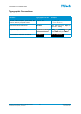
TYPOGRAPHIC CONVENTIONS Typographic Conventions Element Typographic format Example Source code examples, parameters, file names, directory and path names Courier new tt_start_OS; C:\TTTech\TTPos\ GUI menu names and entries Boldface Click File and then Open to open the …dialog. Keyboard keys, GUI buttons Keystroke symbols Command-line interface commands Terminal © TTTech Computertechnik AG 2019. All rights reserved.
IMPORTANT NOTICE Important Notice General The TTE-Switch Lab Space is a non-repair item except for the fuse. Handling Only carry the TTE-Switch Lab Space by holding its carrying handles. Modifying The TTE-Switch Lab Space shall not be opened and the screws shall not be loosened. © TTTech Computertechnik AG 2019. All rights reserved.
HARDWARE SETUP Hardware Setup Required Hardware Several components are needed to get the TTE-Switch Lab Space installed in a rack. The following list shows which of these components are included with the switch and which are not. • Screws and fasteners for rack mounting – tbd • Ethernet cables – not included Installation Instructions Compatible Hardware © TTTech Computertechnik AG 2019. All rights reserved.
1. INTRODUCTION 1 Introduction The TTE-Switch Lab Space is a 25x Ethernet port switch based on the TTE-Controller HiRel (TT6802-2SW-B) and serves as a development platform for TTEthernet. TTEthernet is a fault-tolerant real-time communication protocol for safety-relevant systems that makes it possible to conveniently configure the deterministic processing of critical Ethernet traffic (time-triggered, ARINC 664 P7 [1]) and non-critical, standard Ethernet traffic (IEEE 802.
2. OVERVIEW OF THE TTE-SWITCH LAB SPACE 2 Overview of the TTE-Switch Lab Space Figure 1: The TTE-Switch Lab Space 2.1 Identification Each TTE-Switch Lab Space has a label at its rear that provides the following information: • Product Name: TTE-Switch Lab Space • PNR: Part Number • SER: Serial Number • DOM: Date of Manufacturing • MFR: Manufacturer Figure 2: Product identification label 2.2 • A data matrix with the product serial number on the bottom right.
2. OVERVIEW OF THE TTE-SWITCH LAB SPACE 7. 6 x 100/1000 Mbit/s Ethernet ports (1000Base-T via RJ45) 8. 6 x 100/1000 Mbit/s Ethernet ports (1000Base-X via SFP) NOTE The Ethernet port labeled – is not functional. Figure 4: Rear view of the TTE-Switch Lab Space 9. USB connector (provides access to the DSU/UART1 interface) 10. JTAG connector for factory testing and programming 11. IEC 60320-1 C14 type power connector and a power button.
2. OVERVIEW OF THE TTE-SWITCH LAB SPACE 2.3.2 ARINC 664p7 Implementation • Policing, filtering, and switching engine for bandwidth control and traffic prioritization • Integrity and error checking of frames • 4096 virtual links with up to 8 priorities, with restrictions of their associated ports • 4096 BAGs • BAGs freely configurable from 0.
3. FUNCTIONAL DESCRIPTION 3 Functional Description This section describes the functionality of the TTE-Switch Lab Space. 3.1 Block Diagram Figure 5: Block diagram of the TTE-Switch Lab Space 3.2 Interfaces The TTE-Switch Lab Space features several interfaces that can be divided into networking interfaces, debug and maintenance interfaces, and human-machine interfaces. These interfaces are described in the following sections. 3.2.
3. FUNCTIONAL DESCRIPTION Port Description - This Ethernet port is not functional. 0...18 General purpose, full-duplex RJ45 Ethernet copper ports configurable for 100Base-TX. 19...24 General purpose, 100/1000Base-T. 19...24 General purpose SFP ports configurable for 1000Base-X, suitable to operate 1000BaseX-compliant SFP modules.
3. FUNCTIONAL DESCRIPTION Pin No. Feature Description Default Default/user configuration When connected to GND, the default configuration is loaded. Otherwise, the user configuration is loaded. Input 2,4,6 +3.3VDC Pins connected to +3.3VDC. – 8,10 GND Pins connected to ground. – 9 Table 3: Pin assignment of the GPIO interface 3.2.2.2 RS-422 Interface The RS-422 interface (see Figure 3 on page 13) is used to access the UART0 interface of the TTEController ASIC.
3. FUNCTIONAL DESCRIPTION 3.2.3 Human-Machine Interfaces This section describes the human-machine interfaces of the TTE-Switch Lab Space. 3.2.3.1 Power Button The power button is located right next to the power connector on the rear panel of the switch (see Figure 4 on page 14). To turn on the power, press the power button into the ǀ position. The power button also serves as a disconnect device. NOTE 3.2.3.
3. FUNCTIONAL DESCRIPTION 3.3.2 Size The TTE-Switch Lab Space complies with the IEC 60297 [2] standard and comes with a housing that takes up one rack unit (1U). Size: 346 mm x 483 mm x 44 mm. 3.3.3 Weight The TTE-Switch Lab Space weighs a maximum of 5 kg. 3.3.4 Electrical Characteristics Power Supply The TTE-Switch Lab Space supports the following input voltages: • Voltage: 100 VAC - 240 VAC • Frequency: 60 Hz - 50 Hz Power Consumption The TTE-Switch Lab Space consumes a maximum of 45 W.
4. GETTING STARTED 4 Getting Started The Python scripts mentioned in this and subsequent sections require Python 2.7. Depending on the Python installation on the host system, the Python command will be either python or python2. The examples in this document use python2 for consistency. The Python scripts delivered to the customer were tested on Ubuntu version 14.04. NOTE This section describes how to get started with the TTE-Switch Lab Space in 4 steps. 1.
5. STATE MACHINE 5 State Machine 5.1 State Machine Overview The embedded software of the TTE-Switch Lab Space consists of two main parts: • Bootloader • Firmware The bootloader is stored permanently in the internal ROM of the TTE-Controller HiRel. It cannot be modified or updated. The bootloader initializes the CPU and loads the firmware image. The bootloader then verifies the integrity of this firmware image through a CRC check. If the CRC is successful, the bootloader executes the firmware image.
5. STATE MACHINE User Operations None. Transitions • If successful, the firmware transitions to ADDRESS mode. • In the case of an error, the firmware transitions to ERROR mode. Remarks There is no interaction with the user on the network. 5.2.2 ADDRESS Mode In this mode, the firmware sets the internal software network stack to the data provided by the network configuration. Identification • Shared memory.Operation mode = 0x0000 14FB • No firmware communication on the network • Shared memory.
5. STATE MACHINE Identification • Shared memory.Operation mode = 0x0000 14FC • The firmware responds on the network to ICMP, SNMP, and TFTP requests. • The firmware communicates with best-effort traffic only. • Shared memory.
5. STATE MACHINE Operation • Reconfigure the internal end system and switch engine with the user’s configuration file. • The firmware configures the host interrupts according to the firmware configuration file. • The flash memory is disabled. User Operations None. Transitions • If the reconfiguration is successful, the firmware transitions to CONTROLLER mode. • In the case of an error, the firmware transitions to ERROR mode. Remarks None. 5.2.
6. CONFIGURING THE TTE-SWITCH LAB SPACE 6 Configuring the TTE-Switch Lab Space The device and network configuration files for the TTE-Switch Lab Space are created (see Section 6.1 on the next page) and stored in the flash memory. The firmware maintains a file system on the flash device to this end. The device configuration files can be updated through TFTP only. A Python script lets the user prepare the configuration files for the TFTP transfer.
6. CONFIGURING THE TTE-SWITCH LAB SPACE 6.1 Creating a Switch Configuration In order to upload files to the TTE-Switch Lab Space, it is recommended to use the default configuration. It is also possible to upload files with the user configuration on the condition that the internal end system is reachable with best-effort traffic.
6.
6. CONFIGURING THE TTE-SWITCH LAB SPACE 6.1.1.1 Configuring the Switch In the network description XML file, a switch device must be created. For TTE-Tools version 5.3 or below, the device target is TTE-Switch_Controller_Space_ASIC: 1 2 3 4 5 6 7 8 9 10 11 12 13 14 15 16 17 18 19 20 21 22 23 24 25 26 27 28 29 30 31 PAGE 306. CONFIGURING THE TTE-SWITCH LAB SPACE and 1..n synchronization priorities. • port The attribute port is used to define all the necessary ports of the switch. The user must define 25 physical ports, from P0 to P24. • syncConfig Set the attribute syncRole to syncCompressionMaster when configuring the switch as the TTEthernet compression master and reference a syncPriority, or set the attribute syncRole to syncNone if no TTEthernet clock synchronization is required. The synchronization port AS6802.
6. CONFIGURING THE TTE-SWITCH LAB SPACE • deviceTargets This attribute specifies the name of the device target. For TTE-Tools 5.3 and below, use TTE_ES_Controller_Space_ASIC. For TTE-Tools x.x, use TTE_Switch_Lab_Space_Internal_ES. • hostInterface The attribute HOST.0 specifies the host port and the attribute address of element specifies the MAC address of the internal end system. 6.1.1.
6.
6. CONFIGURING THE TTE-SWITCH LAB SPACE It is possible to use any TFTP client to upload the files. If the files are not uploaded correctly, the Error LED will light up red when trying to enter the user configuration mode (see Table 5 on page 19). It is recommended to use the default configuration when uploading configuration files. 6.2.1 Preparing Files for an Upload To upload a file with TFTP, it must be converted to a specific binary format. The script prepare_tftp_file.
6. CONFIGURING THE TTE-SWITCH LAB SPACE 6.3 Downloading the Switch Configuration Files can be downloaded from the TTE-Switch Lab Space through any TFTP client. The user therefore has to know the preconfigured IP address. In comparison with the upload process (where the file must be converted), a file downloaded from the TTESwitch Lab Space is a plain binary file without any header, hash, ECC protection, or other modification. To upload such a file again, the prepare_tftp_file.py script needs to be run.
6. CONFIGURING THE TTE-SWITCH LAB SPACE Error Possible Cause Mitigation TFTP timeout ● Firmware in wrong mode ● Check the last message on the UART. ● Firmware in ERROR mode ● Check the addresses that was sent by the SNMP SET request. ● Wrong network address (default configuration) Table 7: Recovery from errors © TTTech Computertechnik AG 2019. All rights reserved.
7. DIAGNOSIS 7 Diagnosis Management Information Database The Management Information Database (MIB) describes the managed objects that can be retrieved via SNMP Version 1 (SNMPv1) on UDP port 161. Make sure to use the correct IP address according to your loaded configuration. The default configuration has the IP address 10.10.10.10 (see Section B on page 39). In your preferred SNMP client, make sure to choose SNMPv1 and disable all other versions of the SNMP protocol.
8. TROUBLESHOOTING 8 Troubleshooting 8.1 Basic Checks If you encounter a malfunction of the TTE-Switch Lab Space, there are some basic checks you can perform: • Does the power fuse work? If the power fuse works, but the LEDs of the switch still do not light up, have the AC wall socket checked to see if the wall socket is working as intended. • Is the pin programming of the GPIO interface correct for the desired configuration? • What do the status LEDs display? See Section 3.2.3.
8. TROUBLESHOOTING 8.6 Customer Support Information Company address: TTTech Computertechnik AG Schoenbrunner Strasse 7 A-1040 Vienna, Austria For technical assistance and support regarding TTTech products, please contact our customer support: • E-Mail: support@tttech.com • If there are problems with your TTE-Switch Lab Space, please have the serial number ready to speed up the processing of your support request. © TTTech Computertechnik AG 2019. All rights reserved.
A. DEFAULT CONFIGURATION A Default Configuration The default configuration is part of the firmware image of the switch. Therefore, the default configuration is not part of the user configuration and cannot be changed via TFTP. For default/user configuration selection, see Section 3.2.2.1 on page 17. The settings of the default configuration are: IP: 10.10.10.10 MSK: 255.255.0.0 GW: 10.10.10.1 MAC: A6:A7:A8 :00:01:20 1 2 3 4 Listing 5: Default configuration settings B MIBs B.
B. MIBS 8 tteSwitchingEngineVnV OBJECT IDENTIFIER ::= { ttEthernet 4 } 9 10 11 12 13 14 15 16 tteSweDevId OBJECT -TYPE SYNTAX OCTET STRING (SIZE (0..50) ) ACCESS read -only STATUS mandatory DESCRIPTION "TTE -SWE Device ID ." ::= { tteSwitchingEngineVnV 1 } 17 18 19 20 21 22 23 24 tteSweDevRev OBJECT -TYPE SYNTAX OCTET STRING (SIZE (0..50) ) ACCESS read -only STATUS mandatory DESCRIPTION "TTE -SWE Device revision .
B. MIBS 64 65 66 67 68 69 "COM/MON error detected by the TTE -SwE on the respective port. Each port is represented by a bit , port 0 at bit 0, port 1 at bit 1 and so on. 0: No error occurred . 1: A COM/MON mismatch was detected at the respecitve port ." ::= { tteSwitchingEngineVnV 6 } 70 71 72 73 74 75 76 77 78 79 80 tteSweOutOfMemCond OBJECT -TYPE SYNTAX INTEGER (0..67108863) ACCESS read -only STATUS mandatory DESCRIPTION "Out -of - memory conditions detected by the TTE -SwE. 0: No error occurred .
B. MIBS 120 121 122 123 DESCRIPTION " Smallest correction value ever applied by the clock synchronization algorithm ." ::= { tteSwitchingEngineVnV 10 } 124 125 126 127 128 129 130 131 132 tteSweClockCorrLargest OBJECT -TYPE SYNTAX INTEGER ACCESS read -only STATUS mandatory DESCRIPTION " Largest correction value ever applied by the clock synchronization algorithm ." ::= { tteSwitchingEngineVnV 11 } 133 134 135 136 137 138 139 140 141 142 tteSweNumberOfSyncLoss OBJECT -TYPE SYNTAX INTEGER (0..
B. MIBS 175 176 value also when synchronization is lost ." ::= { tteSwitchingEngineVnV 15 } 177 178 179 180 181 182 183 184 185 186 187 ----------------------------------------- TTE -SWE Ethernet Port Status Table ----------------------------------------tteSweEthPortStatusTable OBJECT -TYPE SYNTAX SEQUENCE OF TteSweEthPortStatusTableEntries ACCESS not - accessible STATUS mandatory DESCRIPTION "TTE -SWE Ethernet Port status table .
B. MIBS 231 232 233 234 235 236 SYNTAX OCTET STRING (SIZE (0..50) ) ACCESS read -only STATUS mandatory DESCRIPTION "Name of the Ethernet port ." ::= { tteSweEthPortStatusTableEntry 1 } 237 238 239 240 241 242 243 244 tteSweEthPortTxBytes OBJECT -TYPE SYNTAX OCTET STRING (SIZE (0..50) ) ACCESS read -only STATUS mandatory DESCRIPTION " Number of bytes sent on the respective Ethernet port .
B. MIBS 286 ::= { tteSweEthPortStatusTableEntry 7 } 287 288 289 290 291 292 293 294 295 tteSweEthPortNoLossUnknownVl OBJECT -TYPE SYNTAX Counter ACCESS read -only STATUS mandatory DESCRIPTION " Number of frames which were dropped because the Virtual Link ID has not been configured for this port .
B. MIBS 341 ::= { tteSweEthPortStatusTableEntry 13 } 342 343 344 345 346 347 348 349 350 tteSweEthPortNoLossRunt OBJECT -TYPE SYNTAX INTEGER (0..255) ACCESS read -only STATUS mandatory DESCRIPTION " Number of frames that do not have a SOF error , alignment error , nor MII error , but are shorter than 64 bytes .
B. MIBS "TTE -SWE memory partition status table for critical traffic ." ::= { tteSwitchingEngineVnV 18 } 397 398 399 tteSweMemPartCtStatusEntry OBJECT -TYPE SYNTAX TteSweMemPartCtStatusEntry ACCESS not - accessible STATUS mandatory DESCRIPTION "TTE -SWE memory partition status table entry for critical traffic .
B. MIBS 21 22 23 24 STATUS mandatory DESCRIPTION " TTEthernet End System Device ID ." ::= { tteEndSystem1 -7 2 } 25 26 27 28 29 30 31 32 tteDevRev OBJECT -TYPE SYNTAX Counter ACCESS read -only STATUS mandatory DESCRIPTION " TTEthernet End System Device Revision Number ." ::= { tteEndSystem1 -7 3 } 33 34 35 36 37 38 39 40 tteSyncState OBJECT -TYPE SYNTAX Counter ACCESS read -only STATUS mandatory DESCRIPTION " TTEthernet Clock Synchronization State .
B. MIBS 73 74 75 76 77 DESCRIPTION "User Configuration Data. This is part of the TTEthernet configuration . NOTE: Only the first 128 characters can be read here ." ::= { tteEndSystem1 -7 8 } 78 79 80 81 82 83 84 85 86 tteMinClkCorr OBJECT -TYPE SYNTAX INTEGER ACCESS read -only STATUS mandatory DESCRIPTION "The smallest correction value ever applied by the clock synchronization algorithm .
B. MIBS Counter , tteMiiErr Counter , tteRxFrames Counter , tteTxFrames Counter , tteVlNotFound Counter 129 130 131 132 133 134 135 136 137 138 } 139 140 141 142 143 144 145 146 tteRxBytes OBJECT -TYPE SYNTAX Counter ACCESS read -only STATUS mandatory DESCRIPTION " Number of received bytes on the channel ." ::= { chStatEntry 1 } 147 148 149 150 151 152 153 154 tteTxBytes OBJECT -TYPE SYNTAX Counter ACCESS read -only STATUS mandatory DESCRIPTION " Number of sent bytes on the channel .
B. MIBS 184 185 186 187 188 189 190 191 192 tteAlignErr OBJECT -TYPE SYNTAX Counter ACCESS read -only STATUS mandatory DESCRIPTION "The number of frames having a length that is not a multiple of 8 bits (at the given line speed )." ::= { chStatEntry 6 } 193 194 195 196 197 198 199 200 201 tteMiiErr OBJECT -TYPE SYNTAX Counter ACCESS read -only STATUS mandatory DESCRIPTION "The number of frames that terminated with the MII error input being asserted .
B. MIBS 237 238 "A table containing partition statistics ." ::= { tteEndSystem1 -7 12 } 239 240 241 242 243 244 245 246 247 parStatEntry OBJECT -TYPE SYNTAX ParStatEntry ACCESS not - accessible STATUS mandatory DESCRIPTION " Information about a particular table row .
B. MIBS 291 292 293 294 295 296 297 298 299 300 ACCESS read -only STATUS mandatory DESCRIPTION "Index of the entry within the IC/ RMTable of the configuration file that was processed when most recently triggering setting the tteRmDropSpecial flag. This value is only valid after reading tteRmDropSpecial first and if tteRmDropSpecial indicates an error . Otherwise its content is undefined .
B. MIBS machine ." ::= { tteEndSystem1 -7 18 } 345 346 347 tteMaxMembVec OBJECT -TYPE SYNTAX INTEGER ACCESS read -only STATUS mandatory DESCRIPTION "The membership vector with the largest number of flags set of all in - schedule integration frames ever processed by the synchronization state machine .
GLOSSARY Terms and Abbreviations Entry Description ASIC Application-Specific Integrated Circuit BAG Bandwidth Allocation Gap BE Best Effort BIST Built-In Self-Test Best-Effort (BE) Traffic Ethernet traffic that is not critical traffic (IEEE 802.3 standard traffic [4]). BE traffic will be serviced with lowest priority. CBIT Continuous Built-In Test COM Communication port, a serial port that acts as a serial communication interface.
Glossary Entry Description SFP Small Form-factor Pluggable, a compact, optical module transceiver. SNMP Simple Network Management Protocol SpW SpaceWire TFTP Trivial File Transfer Protocol TTE Time-Triggered Ethernet (this abbreviations is used as a prefix only). TT Time-Triggered Time-Triggered (TT) Traffic TTEthernet traffic that is used for applications with stringent determinism and real-time requirements (IEEE 1588-compatible clock synchronization service, real-time control [5]).
BIBLIOGRAPHY References [1] ARINC. ARINC Specification 664P7-1, Aircraft Data Network, Part 7, Avionics Full-Duplex Switched Ethernet Network. International Standard, Aeronautical Radio, Incorporated, 2009. [2] IEC. IEC 60297-3-105 Part 3-105: Dimensions and design aspects for 1U chassis. International Standard, International Electrotechnical Commission, 2004. [3] IEEE. 802.1Q™-2011 – Standard for Media Access Control (MAC) Bridges and Virtual Bridged Local Area Networks.
Index — Symbols — TTEthernet implementation. . . . . . . . . . . . . . . . . . . . . . . . . . .14 —A— ARINC 664p7 implementation . . . . . . . . . . . . . . . . . . . . . . . . 15 —S— Standards compliance . . . . . . . . . . . . . . . . . . . . . . . . . . . . . . . 15 State machine . . . . . . . . . . . . . . . . . . . . . . . . . . . . . . . . . . . . . . . 22 —T— Troubleshooting . . . . . . . . . . . . . . . . . . . . . . . . . . . . . . . . . . . . . . 37 —B— Block diagram. . . . . . . . . . . . .