
User Manual


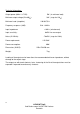

LYDKRAFT ApS
Ved Damhussøen 38,DK 2720 Vanløse
Denmark
3
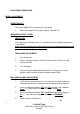
5. Place the voltmeter between
TP4
and
TP6
and adjust the voltage to
50mV
(< +/-2mV) with the multiturn trimpot marked
BIAS
.
6. Place the voltmeter between
TP4
and
TP5
and adjust the voltage to
0V
(< +/-1 mV) with the multiturn trimpot marked
BALANCE
.
7. Repeat step 5-7 until correct.
The adjustment is more quickly made with 2 voltmeters, one hooked up as
in step 2 (step 5) and the other hooked up as in step 3 (step 6)
With correct adjusted bias and balance, the voltage measured between
TP3
and 0V, and
TP6
and 0V, will now be between +13,6V - +16,5V
CHANGE OF OUTPUT IMPEDANCE
1. Remove the bottom cover
2. Beneath the output transformer is the impedance strapping located.
The following scheme shows how the strapping can be altered:
┌───┐ ┌───┐ ┌───┐ ┌───┐
│ ▌ │ │ ▌ │ │ ▌ │ │ │
120
└─▌─┘ └─▌─┘ └─▌─┘ └───┘
(factory setting)
┌───┐ ┌─▌─┐ ┌─▌─┐ ┌─▌─┐
│ │ │ ▌ │ │ ▌ │ │ ▌ │
└───┘ └───┘ └───┘ └───┘
┌───┐ ┌───┐ ┌───┐ ┌───┐
│ ▀▀▀▀▀▀▌ │ │ ▄▄▄▄▄▄ │
30
└───┘ └─▌─┘ └───┘ └───┘
┌───┐ ┌───┐ ┌─▌─┐ ┌───┐
│ ▄▄▄▄▄▄ │ │ ▀▀▀▀▀▀▀ │
└───┘ └───┘ └───┘ └───┘
┌───┐ ┌───┐ ┌───┐ ┌───┐
│ ▄▄▄▄▄▄▄▄▄▄▄▄▄▄▄▄▄▄ │
7,5
└───┘ └───┘ └───┘ └───┘
┌───┐ ┌───┐ ┌───┐ ┌───┐
│ ▄▄▄▄▄▄▄▄▄▄▄▄▄▄▄▄▄▄ │
└───┘ └───┘ └───┘ └───┘