Turbo Air Speeds up the Pace of Innovation M3 Series Reach-Ins Refrigerators & Freezers Installation and Operation Manual Please read this manual completely before attempting to install or operate this equipment. SOLID DOOR REFRIGERATORS M3R19-1-N M3R24-1-N M3R24-2-N M3R47-2-N M3R47-4-N M3R72-3-N M3R72-6-N SOLID DOOR FREEZERS M3F19-1-N M3F24-1-N M3F24-2-N M3F47-2-N M3F47-4-N M3F72-3-N M3F72-6-N www.turboairinc.
CONTENTS PAGE NOTICE 3 FOR HYDROCARBON REFRIGERATION UNITS 4-5 IMPORTANT SAFETY INFORMATION 6-9 SPECIFICATIONS / SERIAL NUMBER 10 NOTICE TO CUSTOMER 11 INSTALLATION 11 CLEANING / CAUTION 12 BASIC OPERATION 13-16 REVERSIBLE DOOR INSTRUCTIONS 17-19 TROUBLESHOOTING 20 STAINLESS STEEL EQUIPMENT CARE & CLEANING 21-22 WARRANTY INFORMATION 23-24 WARRANTY REGISTERATION CARD 27 2
NOTICE • This equipment is not intended for use by persons (including children) with reduced physical, sensory or mental capabilities, or lack of experience and knowledge unless they have been given supervision or instructions concerning the use of this equipment and the hazards involved by a person responsible for their safety.
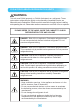
FOR HYDROCARBON REFRIGERATION UNITS WARNING This unit uses R-290 (propane), or R-600a (isobutane) as a refrigerant. These hydrocarbon refrigerants are highly environmentally compatible but also are flammable and combustible. Please read this manual thoroughly before installing and operating the unit. Please take cautious measures to avoid risk of fire or explosion. PLEASE REFER TO THE LABEL INSIDE THE CABINET TO CHECK REFRIGERATION TYPE AND VOLUME. DANGER - Risk of fire or explosion.
FOR HYDROCARBON REFRIGERATION UNITS WARNING • Handle the unit with care in order to avoid any serious damage to the refrigeration system. • The refrigerant tubing, condenser, and evaporator coils are prone to damage while handling, moving, installing, and cleaning the unit, which may lead to fire or even explosion. • Refrigerant squirting out of the pipes could ignite or cause an eye injury.
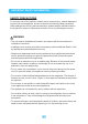
IMPORTANT SAFETY INFORMATION SAFETY PRECAUTIONS To avoid any risk of fire, explosion, electric shock, personal injury, material damage or incorrect use of the appliance, be sure to observe the following safety precautions (After reading these owner’s manual instructions, please keep the manual booklet in a safe place for reference. Remember to hand it over to any subsequent owners). WARNING • The unit must be installed and located in accordance with the manufacturer’s installation instructions.
IMPORTANT SAFETY INFORMATION INSTALLATION & USAGE WARNING • Do not install the unit in a damp place where it could be splashed with water. Incorrect insulation of the electrical parts may cause fire or electric shock. • Do not plug several appliances into the same sockets. This could cause fire due to overheating. • Keep the power plug away from the rear of the cabinet. A damaged power plug may cause fire due to overheating. • Do not spray water directly to the interior or exterior of the appliance.
IMPORTANT SAFETY INFORMATION INSTALLATION & USAGE CAUTION • There is a risk of death from suffocation if a child puts the packing materials on his or her head. • Do not store any articles on top of the appliance. Articles may fall while opening or closing the door, and could cause personal injury or material damage. • Do not store pharmaceutical products, scientific materials or other temperature-sensitive products in the refrigerator.
IMPORTANT SAFETY INFORMATION PROPER DISPOSAL OF OLD APPLIANCE For environmental purposes, refrigeration appliances must be properly disposed. This applies to your old appliance, and at the end of its service life, for your new appliance as well. WARNING Before disposing of old appliances, make them inoperable. Remove plug from mains, severe the power cable, and remove or destroy any snap or latch closures.
SPECIFICATIONS Refrigerators MODEL COMP H.P. V/Hz REFRIGERANT AMPS WEIGHT M3R19-1-N 1/4 115V/60Hz R-290 2.5 194 lbs. M3R24-1-N 1/4+ 115V/60Hz R-290 2.5 270 lbs. M3R24-2-N 1/4+ 115V/60Hz R-290 2.5 270 lbs. M3R47-2-N 1/3 115V/60Hz R-290 2.8 401 lbs. M3R47-4-N 1/3 115V/60Hz R-290 2.8 401 lbs. M3R72-3-N 3/8 115V/60Hz R-290 5.6 559 lbs. M3R72-6-N 3/8 115V/60Hz R-290 5.6 559 lbs. Freezers MODEL COMP H.P.
NOTICE TO CUSTOMER Loss or spoilage of products in your refrigerator/freezer is not covered by warranty. In addition to following recommended installation procedures, you must run the refrigerator/freezer 24 hours prior to usage. INSTALLATION 1. LOCATION - Allow adequate space and install the refrigerator on a firm and level floor. If the appliance is not level, there may be unusual noises and poor cooling performance. 2.
CLEANING Before cleaning, unplug the unit and disconnect the power. Wipe and clean the inside and outside of appliance with a damp cloth. 1. CLEANING THE INTERIOR AND EXTERIOR - The interior and exterior of the unit can be cleaned using warm water and soap. - Do not use an abrasive cleaner because it will scratch the surface. 2. CLEANING THE CONDENSER COIL - To maintain proper refrigeration performance, the Condenser coil must be free of dust, dirt, and grease. This will require periodic cleaning.
BASIC OPERATION REFRIGERATORS M3R19-1-N M3R24-1-N M3R47-2-N M3R72-3-N M3R24-2-N M3R47-4-N M3R72-6-N 1. Plug in and turn on the power switch located on the control box. The Display panel will be lighted and make a beep sound. The compressor will begin to run. 2. The default temperature setting is No. “4”. 3. The compressor is automatically cycled by the electronic controller (PCB, RD-Sensor). 4. The Defrost cycle is automatically controlled by the PCB. 5.
UP/DOWN BUTTON (Temperature control button) 1. By pushing the up/down button, you can set the inside temperature level from ‘1’ to ‘7’. 2. If you want to lower the temperature, push the Down button to increase and light higher number. INNER TEMPERATURE DISPLAY 1. It displays the inside temperature. 2. Display range is 14˚F to 69˚F (-10˚C ~ +20˚C). 3. When the inside temperature is lower than 14˚F, the panel will display ‘ and, higher than 69˚F, the panel will display ‘ ’. ’. FAN RUNNING 1.
BASIC OPERATION M3F19-1-N M3F24-1-N M3F47-2-N M3F72-3-N FREEZERS M3F24-2-N M3F47-4-N M3F72-6-N 1. Plug in and turn on the power switch located on the control box. The Display panel will be lighted and make a beep sound. The compressor will begin to run. 2. The default temperature setting is No. “4”. 3. The compressor is automatically cycled by the electronic controller (PCB, RD-Sensor). 4. The Defrost cycle is automatically controlled by the F-sensor, and the PCB. 5.
UP/DOWN BUTTON (Temperature control button) 1. By pushing the up/down button, you can set the inside temperature level from ‘1’ to ‘7’. 2. If you want to lower the temperature, push the Down button to light and increase higher numbers. DEFROST 1. The electronic defrost controller is set at the factory to provide a defrost cycle every 6 hours (4 times per a day). 2. The panel displays “ ” during the defrost cycle. INNER TEMPERATURE DISPLAY 1. It displays the inside temperature. 2.
REVERSIBLE DOOR INSTRUCTIONS (For M3R19-1-N / M3R24-1-N / M3F19-1-N / M3F24-1-N) 1. TOP GRILLE (T) AND TOP GRILLE (B) A. Disassemble the top grille fixture as below. D. Unscrew the screws located on the bottom of top grille (B). B. Lift top grille (T) as illustrated below. E. Pull out the harness of the display PCB and the harness of the door s/w located on back of top grille (B). CAUTION: When unscrewing, hold top grille. Falling down the top grille cause bruise. C. Unscrew screws on top grille (B).
REVERSIBLE DOOR INSTRUCTIONS (For M3R19-1-N / M3R24-1-N / M3F19-1-N / M3F24-1-N) 2. REPLACING DOOR A. Unscrew screws located on top hinge (right). C-2. Disassemble bottom hinge (left). B. Lift the door, then remove it. C-1. Disassemble the top hinge (left). D. Screw stopper plate on top hinge (right).
REVERSIBLE DOOR INSTRUCTIONS (For M3R19-1-N / M3R24-1-N / M3F19-1-N / M3F24-1-N) G. Assemble stopper plate in original positions. E. Disassemble stopper plate which located on bottom hinge (right), then assemble bottom hinge (right) on position of top hinge (left). H. Assemble the door, then rotate it about 180 degrees.
TROUBLESHOOTING SYMPTOMS CAUSES SOLUTIONS Cooler is freezing food. • Thermostat set too cold. • Turn the thermostat setting to a higher temperature position The unit does not refrigerate at all. • There is a power connection failure problem. • Check the power cord and plug in correctly. The unit does not refrigerate well. • The unit is in sunlight or near a heating device. • The unit contains hot food or too much food. • The unit door is opened too frequently or left open too long. • The temp.
STAINLESS STEEL EQUIPMENT CARE AND CLEANING CAUTION : Do not use any steel wool, abrasive or chlorine based products to clean stainless steel surfaces. There are three basic things which can break down your stainless steel’s passivity layer and allow corrosion to occur. 1) Scratches from wire brushes, scrapers, and steel pads are just a few examples of items that can be abrasive to stainless steel’s surface. 2) Deposits left on your stainless steel can leave spots.
STAINLESS STEEL EQUIPMENT CARE AND CLEANING 4. Water Treatment To reduce deposits, soften the hard water when possible. Installation of certain filters can remove corrosive and distasteful elements. Salts in a properly maintained water softener can be to your advantage. Contact a treatment specialist if you are not sure of the proper water treatment. 5. Maintaining the cleanliness of your food equipment Use cleaners at recommended strength (alkaline, alkaline chlorinated or non-chloride).
WARRANTY INFORMATION THREE (3) YEAR WARRANTY Warranty Claims... All claims for parts or labor must be made directly through Turbo Air. All claims should include: model number of the unit, the serial number of the cabinet, proof of purchase, date of installation, and all pertinent information supporting the alleged defect. In case of compressor replacement under warranty, either compressor or compressor tag must be returned to Turbo Air along with above listed information.
WARRANTY INFORMATION What is Not Covered by This Warranty... Turbo Air’s sole obligation under this warranty is limited to either repair or replacement of parts, subject to the additional limitations below. This warranty neither assumes nor authorizes any person to assume obligations other than those expressly covered by this warranty. NO CONSEQUENTIAL DAMAGES.
NOTE 25
NOTE 26
Warranty information card must be submitted via post mail or electronically on our website at www.turboairinc.com/registration within 7 days from the date of purchase. Failure to comply may result in your warranty being voided. WARRANTY REGISTRATION CARD MAIL CARD IMMEDIATELY OR GO TO ONLINE REGISTRATION AT www.turboairinc.
4184 E. Conant St., Long Beach, CA 90808 Toll Free: 1-800-381-7770 Fax: 310-900-1033 Email: warranty@turboairinc.com www.turboairinc.