Commercial Refrigerator & Freezer Service Manual Solid Door Model No.
TABLE OF CONTENTS 1. FEATURE CHART 1-1. FRONT VIEW 1-2. SIDE VIEW 2. WIRING DIAGRAM 2-1. REFRIGERATOR (1DOOR) : TSR-23SD 2-2. FREEZER (1DOOR) : TSF-23SD 2-3. REFRIGERATOR (2DOOR) : TSR-49SD 2-4. FREEZER (2DOOR) : TSF-49SD 2-5. REFRIGERATOR (3DOOR) : TSR-72SD 2-6. FREEZER (3DOOR) : TSF-72SD 3. PART DETAILS 3-1. TOP GRILLE 3-2. REFRIGERATION COMPARTMENT 3-3. ELECTRICAL BOX 3-4. DOOR 3-5. COOLING COMPARTMENT 4. MAIN COMPONENTS 4-1. COMPRESSOR 4-2. COMPRESSOR RELAY 4-3. CONDENSER DRYER 4-4. CAPACITOR 4-5.
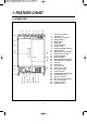
1. FEATURE CHART 1-1.
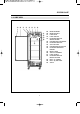
FEATURE CHART 1-2. SIDE VIEW l ; z x c v b n m , !@# .
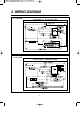
2. WIRING DIAGRAM 2-1. TSR-23SD WIRING DIAGRAM 2-2.
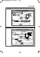
WIRING DIAGRAM 2-3. TSR-49SD WIRING DIAGRAM 2-4.
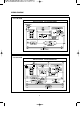
WIRING DIAGRAM 2-5. TSR-72SD WIRING DIAGRAM 2-6.
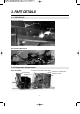
3. PART DETAILS 3-1. TOP GRILLE Door Lock, Switch Door Lock Door Switch Transformer, Main P.C.B Harness Transformer Main PCB 3-2.
PART DETAILS Drain Pan Assembly Drain Wicking Bar Drain Pan Drain Wicking Pads Condenser Fan Motor Assembly Condenser Fan Motor Bracket Condenser Fan Motor Blade 3-3. Electrical Box Power Bushing Power Relay (Comp.
PART DETAILS 3-4. Door Gasket Gasket 3-5.
PART DETAILS Freezer Duct & Refrigerator Duct (TSR-23SD, TSF-23SD Type) Evaporator Fan Motor Guard Duct (A) Duct (B) Freezer Evaporator, Fan (TSF-23SD) Lamp & Fan Motor Connectors Evaporator Fan Motor Blade Evaporator Evaporator Thermal Evaporator Coil Heater F-Sensor 10 Heater Connectors & Sensor Connectors
4. MAIN COMPONENTS 4-1. COMPRESSOR Model TSR-23SD Refrigerant TSR-49SD TSF-23SD R-134a TSF-49SD R-404a Voltage TSR-72SD R-134a 115V / 60Hz TSF-72SD R-404a 208/230 Comp. Model HBL27YE-1 SK6A1C-H2Y AEA2411ZXA AJA2425ZXA AKA4476YXA CAJ2446Z Part code 3952127G10 3020014540 30200L0100 30200L0200 30200A4700 30206Q3600 CSR RSIR CSIR CSIR CSIR CSR TSF-23SD TSF-49SD TSR-72SD TSF-72SD Strating type 4-2.
MAIN COMPONENTS 4-5. EVA FAN MOTOR Model TSR-23SD TSR-49SD TSF-23SD Voltage TSF-49SD TSR-72SD TSF-72SD TSR-72SD TSF-72SD 115V / 60Hz Motor Model IS4420DWSN-2A Part code 3963328120 4-6. CONDENSOR FAN MOTOR Model TSR-23SD TSR-49SD TSF-23SD Voltage Motor Model TSF-49SD 115V / 60Hz 220V/60Hz IS4420DWSG-1 IS4420DWSQ-1 3963220410 3963322020 Part code 4-7. EVA DEFROST HEATER Model TSR-23SD TSR-49SD TSF-23SD Voltage TSF-49SD TSR-72SD TSF-72SD 115V / 60Hz Spec.
6.
PART-LIST OF SOLID DOOR MODEL Part name Code Material Description CAPILLARY TUBE (A) 30244Q1000 C1220T L2263 IDø3.56 CAPILLARY TUBE (B) 30244Q1100 C1220T L3505 IDø2.0 CONDENSER DRYER 30268L0300 C1220T XH-9 50g ø3.1 CONDENSER DRYER 30268L0400 C1220T XH-9 50g ø3.5 CONDENSER DRYER 30268Q0100 C1220T XH-9 50g ø5.0 CONDENSER DRYER 30268Q0210 C1220T XH-9 50g ø5.
PART-LIST OF SOLID DOOR MODEL Part name Code Material Description Model R-23S R-49S F-23S F-49S R-72S F-72S 30211J0103 HIPS 1 1 1 1 DRAIN WICKING BAR 30230J0700 PVC-H 1 1 1 1 DRAIN WICKING BAR 30230L0100 PVC-H DRAIN WICKING PADS 30245L1000 PULP T2.5 DRAIN WICKING PADS 30245A0700 PULP T2.5 5 5 5 1 1 1 1 1 DRAIN PAN 1 1 5 5 5 Evaporator DRAIN CAP 30209L0200 PA-6 1 EVAPORATOR DRAIN PAN 30211L0501 A1100P-H14 0.
PART-LIST OF SOLID DOOR MODEL Part name DUCT (A) Code Material Description 1 30269L0304 SUS 304 DUCT (A) 30269L0404 SUS 304 DUCT (A) 30269Q0500 SUS 304 DUCT (B) 30269L0507 SUS 304 DUCT (B) 30269L0606 SUS 304 DUCT (B) 30269Q0400 SUS 304 Model R-23S R-49S F-23S F-49S R-72S F-72S 1 1 1 1 1 1 1 1 1 1 1 Top Grille Panel TOP GRILLE PANEL ASSEMBLY 30224L0450 TOP GRILLE PANEL ASSEMBLY 30224L0230 TOP GRILLE PANEL ASSEMBLY 30224L0350 TOP GRILLE PANEL ASSEMBLY 30224L0130 TOP GRILLE PAN
PART-LIST OF SOLID DOOR MODEL Part name Code Material BOTTOM GRILLE ASSEMBLY 30224L1400 STS304-HL BOTTOM GRILLE ASSEMBLY 30200Q4100 STS304-HL Description Model R-23S R-49S F-23S F-49S R-72S F-72S 1 1 1 1 Lamp 1 1 1 1 2 2 30227L0900 1 1 1 1 2 2 LAMP BULB 30236L0100 1 1 1 1 2 2 LAMP SOCKET 30279L0100 MEDIUM BASE L-124B-PVC 1 1 1 1 2 2 LAMP SHIELD 30214L3200 PP LAMP HARNESS MILKY 25W/120V Shelf SHELF STANDARD 30220L1001 STS304-2B 0.
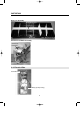
7. REPLACEMENT OF MAIN COMPONENTS 7-1. TOP GRILLE PARTS - MAIN PCB or TRANSFORMER - DISPLAY PCB - DOOR LOCK or POWER SWITCH (ROCKER SWITCH) - DOOR SWITCH A. Unscrew the screw located both sides of top grille panel.
REPLACEMENT OF MAIN COMPONENTS B. Unscrew the screws located on top of top grille panel.
REPLACEMENT OF MAIN COMPONENTS C. Unscrew the screws located on bottom of top grille panel. * Caution : When unscrewing, hold the top grille panel. Falling down top grille may cause bruise. D. Place the top grille panel on the top of the cabinet. E. You can replace PCB, Transformer.
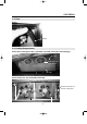
REPLACEMENT OF MAIN COMPONENTS F. Pull out the harness located back of top grille panel. You can separate top grille panel. You can replace power switch(rocker switch), door switches(lamp switch) and control board housing. G. To re-assemble, do reversed in order.
REPLACEMENT OF MAIN COMPONENTS 7-2. REPLACING DOOR A. Disassemble top grille panel as described section 7-1 A.B.C.D. B. Remove Bottom Grille by unscrewing the four screws located on each side of the Bottom Grille. C. Open the electrical box. Then uncap the door heater wire.
REPLACEMENT OF MAIN COMPONENTS D. The figure of the disassembled top grille panel. E. Unscrew the hinge. F. Unscrew the last screw with pushing the hinge. G. After unscrewing, the hinge will rotate about 90˚(CCW), of itself.
REPLACEMENT OF MAIN COMPONENTS H. Lift the door and pull out the door heater’s lead wire. I. Replace the door with the new one. J. Ready the hinge as below. It is important to set initial position (angle).
REPLACEMENT OF MAIN COMPONENTS K. Initial position of the hinge must be as below. L. Turn the hinge 90˚ CW. This turning causes torsion strength of the bar spring that shuts the door(s) automatically. M. Screw the hinge with pushing it. After installation of the door(s), assemble the top grille panel.
REPLACEMENT OF MAIN COMPONENTS 7-3. REFRIGERATION COMPARTMENT’S PARTS A. Disassemble lamp shield. - LAMP BULB or LAMP SHIELD - EVAPORATOR FAN MOTOR - F/D SENSOR or R/D SENSOR - EVAPORATOR DEFROST HEATER - EVAPORATOR COIL B. Disassemble Duct (A). C. Pull out the lamp harness.
REPLACEMENT OF MAIN COMPONENTS D. Disassembe duct (B). E. Pull-out the evaporator drain pan heater’s leadwire. F. Figure of disassembled refrigeration compartments. In this situation, you can replace fan motor, F/D-sensor, Evaporator coil, ETC.
REPLACEMENT OF MAIN COMPONENTS G. Replacing evaporator fan motor F-1. Pull out the fan motor’s connector. F-2. Unscrew the four screws which located on bottom of fan motor. H. Replacing F/D-Sensor or R/D-Sensor H-1. F-Sensor of Freezer Unscrew as illustrated below and pull-out the F-Sensor from the cover.
REPLACEMENT OF MAIN COMPONENTS H-2. D-Sensor of Freezer (Evaporator Defrost Sensor) Disassemble the D-Sensor from evaporator’s end plate. D-Sensor (Blue Color) H-3. R-Sensor of Refrigerator Unscrew as illustrated below and pull-out the R-Sensor from the cover.
REPLACEMENT OF MAIN COMPONENTS H-4. D-Sensor of Refrigerator Remove the absorber pad at the end of thermo-pipe and pull-out the D-Sensor. Thermo-Pipe D-Sensor (Blue Color) H-5. F/D Sensor or R/D Sensor After unplug each sensor, pull-out the sensor’s lead wire.
REPLACEMENT OF MAIN COMPONENTS REPLACING EVAPORATOR DEFROST HEATER (FREEZER ONLY) A. After disassembling the duct(A) and the duct(B), get ready as below for replacing the evaporator defrost heater. B. Pull out the pins from the bottom of the evaporator using the nipper, etc. H. Split the hooks of the evaporator.
REPLACEMENT OF MAIN COMPONENTS D. After removing all pins, disconnect the connectors from the thermal fuse and the main E. Take apart the evaporator defrost heater from the evaporator.
REPLACEMENT OF MAIN COMPONENTS F. Install the new evaporator defrost heater in original position. G. Pat the evaporator defrost heater with the soft hammer. H. Pinch the hooks of the evaporator.
REPLACEMENT OF MAIN COMPONENTS I . Assemble the pins in original positions. J. Connect the connectors of the evaporator defrost heater to them of the thermal fuse * NOTE Why is always 115 voltage detected between connectors of the evaporator defrost heater in the main harness? The SNUBBER(located Main PCB) holds two AC power lines simultaneously. The SNUBBER prevents Main PCB malfunction from sparks occurred by other electrical component’s ON/OFF.
REPLACEMENT OF MAIN COMPONENTS 7-4. CONDENSING UNIT - Condensing units : Compressor, Condenser Fan Motor, Condenser Coil, Condenser Dryer.... - Others : Compressor Power Cord (Relay harness), Main Power Cord, Electrical Box, ETC. A. Disassemble Bottom Grille as described section 7-2. B. B. Unscrew two screws as below. C. Unplug the compressor’s power plug.
REPLACEMENT OF MAIN COMPONENTS D. Pull-out the condensing unit.
REPLACEMENT OF MAIN COMPONENTS 7-5. REPLACING CABINET FRAME HEATER (and/or) MULLION HEATER A. Insert the and edge of ‘–’type screw driver into the gap between the frame and the frame cover. B. Take apart the frame cover from the frame. C. Separate the frame cover by sliding the screw driver. D. Do just like above instructions in other parts (bottom side, right side and top side).
REPLACEMENT OF MAIN COMPONENTS E. Below picture shows the inlet of the cabinet frame heater toward the electrical box. F. Uncap connectors of the cabinet frame heater. G. Pull out the heater wire from the inlet. H. Insert the new cabinet frame heater wire to the inlet, after surrounding it along the frame.
REPLACEMENT OF MAIN COMPONENTS I. Assemble the frame cover with the frame. Push and slide the frame cover toward corner. J. Fit the end lines of the frame cover each other. K. Fit the other side of the frame cover, too. L. Pat the frame cover with the soft hammer, etc.
REPLACEMENT OF MAIN COMPONENTS M. Do like above instructions in other parts (Left side, right side and top side).
REPLACEMENT OF MAIN COMPONENTS N. Unscrew the screws from the mullion. O. Take apart the mullion cover from the mullion. P. Take care for the mullion heater not to be hurt. (It does not matter, if this heater is out of order).
REPLACEMENT OF MAIN COMPONENTS Q. Pull out the insulator from inside. R. Uncap connectors of the mullion heater. S. Pull out the heater wire from the inlet.
REPLACEMENT OF MAIN COMPONENTS T. Pull out the mullion cover(SUS) from the mullion cover (ABS). U. Change the old mullion heater and install the new one with the gap between wires 1.2 inch. V. Insert the mullion cover(SUS) into the original pisition.
REPLACEMENT OF MAIN COMPONENTS W. Connect the heater wires with the main harness and the electrical box harness. X. Cover the caps on the connection parts and press them tightly.
VISION CREATIVE, INC. 중구 남대문로 5가 526 대우재단빌딩 16층 담 당 MODEL BUYER 일 정 제 판 규 격 MEMO TEL TSR-23SD/49SD, TSF-23SD/49SD(영) 성기린 님 1차 2001.10.20 6차 2001.12.15 2차 2001.10.24 7차 2001.12.18 3차 2001.11.2 8차 2001.12.20 4차 2001.11.6 9차 2001.12.27 5차 2001.12.5 10차 인쇄 한(2002.1.11) 고흥 (2001.10.24)-(4,5,11,15,16,17,18,19,21,22,24,31,32,33,35p)-15page 수정 (2001.11.2)-(2,3,4,6,7,8,9,11,20,21,22,23p)-12page 수정 (2001.11.6)-(2p)-1page 재수정 (2001.11.