Turbo Air Speeds up the Pace of Innovation Underbar Equipment Beer Dispensers Installation and Operation Manual Please read this manual completely before attempting to install or operate this equipment! TBD-1SD TBD-2SD TBD-3SD TBD-4SD TBD-1SB TBD-2SB TBD-3SB TBD-4SB SD series: Stainless Steel Exterior SB series: Black Laminated Vinyl Exterior or Black Powder Coating Exterior www.turboairinc.
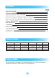
CONTENTS PAGE SPECIFICATIONS 2 SERIAL NUMBER 2 INSTALLATION OF THE CASTERS 3 Draft Arms Towers Installation Schematic Diagram 3 Beer Line & CO2 Line Installation Schematic Diagram 4 Caution "IMPORTANT" 5-6 INSTALLATION 7 CLEANING 8 BASIC OPERATION 9 TROUBLESHOOTING 10 WARRANTY 11-13 SPECIFICATIONS MODEL TBD-1SD/SB TBD-2SD/SB TBD-3SD/SB TBD-4SD/SB COMPH.P. 1/10 1/3 1/3 1/3 V/Hz 115V/60Hz 115V/60Hz 115V/60Hz 115V/60Hz REFRIGERANT R-134a R-134a R-134a R-134a AMPS 4.0A 7.0A 7.0A 7.
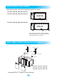
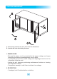
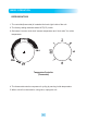
INSTALLATION OF THE CASTERS According to model, refer to the assembly position of casters. TCB-2SD, TBD-2SD, TBB-2SB, TBB-2SG TCB-3SD, TBD-3SD, TBB-3SB, TBB-3SG TCB-4SD, TBD-4SD, TBB-4SB, TBB-4SG This picture is a plan view of bottom cabinets. CB is an abbreviation of the caster with a brake. Other casters don't have a brake.
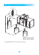
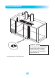
BEER LINE & CO2 LINE Installation Schematic Diagram Distributor Fixture CO2 Line CO2 Beer Line#1 Beer Line#2 Beer #1 Beer #2 TCB-2SD, TCB-3SD, TCB-4SD TBD-2SD, TBD-3SD, TBD-4SD TBD-2SB, TBD-3SB, TBD-4SB * Assemble BEER LINE & CO2 LINE as above drawing.
CAUTION "IMPORTANT" DIRECT DRAW On direct-draw dispensers the drain is located at the front of the cabinet. To plumb in the drain, connect 5/8” P.V.C. pipe to the 5/8” barbed fitting supplies with the unit. * Don't pull out or Turn drain line.
CAUTION "IMPORTANT" A. Excessively opening the door will cause the breakdown. B. Handle with care as shutting the door. 1. POWER CORD - Be sure the power cord is connected to the proper voltage, and amps should be run before connecting power cord to outlet. - A protected circuit of the correct voltage and amperage must be run for connection of the line cord. - Unplug the unit, whenever performing maintenance functions or cleaning the refrigerated cabinet.
INSTALLATION 1. GOOD AIR CIRCULATION - Do not place any object that will restrict air flow in front or back grills - Turbo air highly recommends that there is ample space in rear of unit. 3 inches or more is best 2. PLACE ON STRONG GROUND - Be sure the location chosen has a floor strong enough to support the total weight of the cabinet and contents 3. DO NOT PLACE NEAR HEAT - Be sure to avoid hot corners and locations near stoves - High ambient temperature will make cooling efficiency lower 4.
CLEANING Before cleaning, unplug the unit. 1. CLEANING THE INTERIOR AND EXTERIOR - The interior and exterior of the unit can be cleaned using warm water with soap - Do not use an abrasive cleaner because it will scratch the surface 2. CLEANING THE CONDENSER FINS - To maintain proper refrigeration performance, the Condenser coil must be free of dust, dirt, and grease This will require periodic cleaning.
BASIC OPERATION REFRIGERATORS 1. The controller(thermostat) is located at the back right inside of the unit. 2. The factory setting maintains about 38˚F(3˚C) inside. 3. Set toward “counter clock wise” warmer temperature and “clock wise” for colder temperature. Temperature Controller (Thermostat) 4. The thermostat controls compressorʼs cycling by sensing inside temperature. 5. When unit will not be used for a long time, unplug the unit.
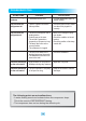
TROUBLESHOOTING SYMPTOMS CAUSES SOLUTIONS Cooler is freezing products • Thermostat set too cold. • Turn the temperature dial to a warmer setting. The unit does not refrigerate at all • There is a power connection failure problem. • Check the power cord to make sure the unit is pluged in it correctly. The unit does not refrigerate well • The unit is in sunlight or near a heating device. • Product was put in warm. • The unit lid is opened too frequently or left open too long. • The temp.
MANUFACTURING COMPANY THREE YEAR WARRANTY Turbo Air warrants to the original purchaser of every new Turbo Air refrigerated unit, the cabinet and all parts thereof, to be free from defects in material or workmanship, under normal use and service, for a period of three (3) year from the date of original installation or 39 months after shipment date from Turbo Air , whichever occurs first.
What is NOT covered by this warranty Turbo Airʼs sole obligation under this warranty is limited to either repair or replacement of parts, subject to the additional limitations below. This warranty neither assumes nor authorizes any person to assume obligations other than expressly covered by this warranty. 1. WARRANTY IS NOT TRANSFERABLE. This warranty is not assignable and applies only in favor of the original purchaser/user to whom delivered.
Warranty Claims... All claims for parts or labor must be made directly thorough Turbo Air. All claims should include: model number of the unit, the serial number of the cabinet, proof of purchase, date of installation, and all pertinent information supporting the alleged defect. In case of compressor replacement under warranty, either compressor or compressor tag must be returned to Turbo Air along with above listed information. Failure to comply with warranty policies will result in voiding claims.