
- Turbo Chef Speed Cook Oven Service Manual


63
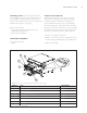
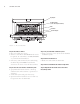
HIGH H BATCH SCHEMATIC
H
HB OVEN SCHEMATIC
Figure 61. Inside of fold-out page. Rev 2 Board,
VFD Display, Single Phase, 280/240 VAC, 60 Hz
NOTE: Schematic shows the oven with door open
and without power applied.
Color Code (Line Voltage)
BL – Blue = Line V (208/240)
BR – Brown = Line V (208/240)
OR – Orange = 240 Line Input for Tap 3 on
all Transformers
BK – Black = Hi-Temp 240 VAC Wire
Color Code (Low/Control Voltage)
BK – Black = 24 VDC Common
OR – Orange = Status Input
WH – White = Control Input
RD – Red = +24
VDC
Line Voltage Components
Blower M
otor
Blower M
otor Controller
Cooling F
ans
Fuses
Heater Element
Power Supply, +24VDC
Rack Oscillator Motor
R
elay
Solid State Relay
Thermostat – Cooling Fan
Thermostat – H
i-Limit
Voltage Sensor Module
W
iring Harness – Line Voltage
Low Voltage Components
Cable – Smart Card Connector
Display, VFD
Door Switch
I/O Control Board
Keypad
Ribbon Connector – Display
Smart Card Reader
Thermocouple – CC
Thermocouple – EC
W
iring Harness – Low Voltage
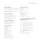
I/O CONTROL BOARD COMPONENT IDENTIFICATION
AND TEST POINT LOCATIONS
Figure 62, page 64
J2
40-Pin Connector for LV Harness
J3
3-Pin Connector for VFD Display
J4 14-P
in Connector for K
eypad
J5 26-Pin Connector for Display Data
J6 RS-232 Connector
(for computer hookup
, if necessary)
RJ11 Connector for Smart Card Cable
U15 EPROM Socket
P1 Voltage Refer
ence 0-5 VDC
P3 Blower Controller Pin Configuration
SKP1 Beeper
R51 Beeper Volume Adjustment