
Residential Single and Double Wall Oven Service Manual


APPENDIX REPLACING OVEN COMPONENTS
A.11
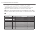
Item Description Item Part # Hardware Description Hardware Part Number(s)
Bracket, Display, Lower RWD-9142 Screw, #8 x 1/2, PHPH, PLT 101689 (x2 each)
Control Housing Assembly
(see pages A.12-A.13)
N/A Screw, #8 x 3/4, PPHD, PLT-STL 104178 (x5)
CookWheel Support Plate RWD-9455 None None
Dial, Oven Mode RWD-9379 None None
Dial, Temperature RWD-9380 None None
Display, Lower RWD-9295 None None
Diverter, Vent Outlet RWD-9584
Screw, #8 x 3/8 PH MOD TRUSS CRES
Clip, Press-On Nut, #8, .5 x .5
101682 (x3)
104189
Light Switch 104141 Screw, #8 x 1/2, PHPH, PLT 101689 (x2)
Outer Frame, DWO RWD-3006 None None
Outer Frame, SWO RWS-9005 None None
Switch Assembly, Mode RWD-9257 Screw, #8-32 x 3/8, PPHD, INT SEMS, SS 102921 (x2)
Switch Assembly, Temperature RWD-9258 Screw, #8-32 x 3/8, PPHD, INT SEMS, SS 102921 (x2)
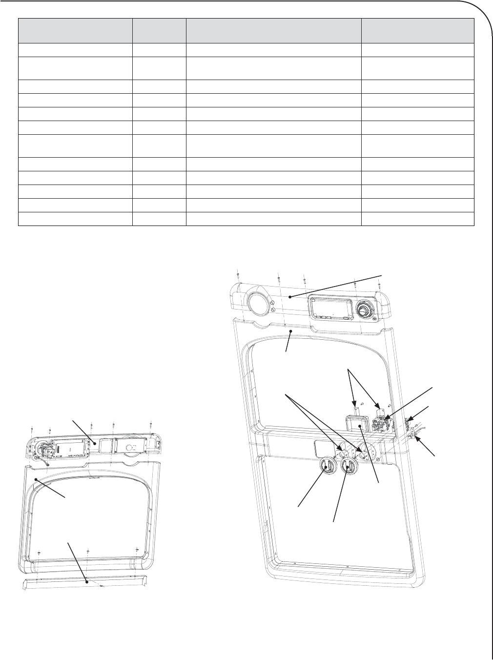
Control Housing
Assembly
Display, Lower
Outer Frame, DWO
Switch Assembly, Mode
Switch Assembly,
Temperature
Light Switch
CookWheel
Support Plate
Dial, Temperature
Dial, Oven Mode
Bracket, Display, Lower
Figure A.4: Front Trim Assembly Details, DWO
Control Housing Assembly
Outer Frame, SWO
Diverter, Vent Outlet
Figure A.3: Front Trim Assembly Details, SWO