
User's Manual


3
(COMx; x=1,2,3... on IBM and compatible PCs).
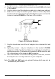
4. Plug the telephone cable into the connector marked LINE on the back
of the modem.
5. Plug the other end of the telephone cable into a telephone wall jack.
6. Make sure to verify the modem power switch is in the off position
(located on the front panel). Plug the AC adapter's power cord into the
connector marked POWER on the back of the modem.
7. Plug the transformer end of the AC adapter into a standard AC wall
outlet
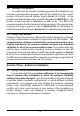
8. Optionally connect : (1) your telephone to the modem's PHONE
connector. Lift the handset and listen for a dial tone to check for a
working connection.(2) a speaker to the modem's SPK connector, and
(3) a microphone to the modem's MIC connector.
9. Turn on the modem. The modem should perform a self-test, and then
be ready for use. You may now turn on your computer.
Note: The SPK and MIC jacks are optional feature which may not be
available on your modem.
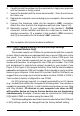
Figure 2-1 External Modem
MIC