
User's Manual


4
2.1.1 Indicator Lights
Your modem (external model only) features LED indicators on the
front panel that report modem status:
MR
Modem Ready On when modem is ready to work
TR
Terminal Ready On when DTR signal is active
SD
Send Data On when modem is transmitting data to remote modem
RD
Receive Data On when modem is receiving data from remote modem
OH
Off Hook On when modem is off hook
CD
Carrier Detect On when remote carrier has been detected
RS
Request to Send On when RTS signal is active
CS
Clear to Send On when CTS signal is active
This completes the external modem installation. Proceed to
Section
3
for information on installing and configuring your communication soft-
ware.
2.2 Internal Modem Installation
The following steps provide instructions for installing your internal
modem.
CAUTION:
Before removing the cover from your computer, turn off
and unplug the computer and all attached external peripherals. Prior to
removing the modem from its antistatic bag, discharge any static electricity
from your body by touching any metal surface.
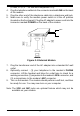
1. Turn off the computer and unplug
it from the AC outlet.
2. Remove the computer's cover, in
accordance to its owner's manual.
3. Select any available ISA bus slot.
The modem will work in either 8 or
16 bit slots.
4. Unscrew and remove the slot cover.
Set the screw aside for later use.
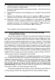
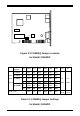
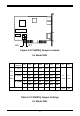
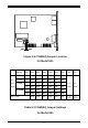
5. For non-PnP installation, please
read thoughout
Section2.2.1
to set
the proper COM port and IRQ. For
PnP installation, please set the short
caps to PnP mode. (Refer to Table
2-1~2-3)
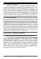
Figure 2-2
or
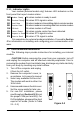
SPKR
PHONE
LINE
MIC
SPKR
LINE
MIC