ASPECT TA-500 SYSTEMS TA-500 TA-500DP TA-500t TA-500tDP TA-500H TA-500HDP TA-500HM USER MANUAL Turbosound Ltd. Star Road, Partridge Green West Sussex RH13 8RY United Kingdom Tel: +44 (0)1403 711447 Fax: +44 (0)1403 710155 web: www.turbosound.com Issue 1.1 © Turbosound Ltd.
user manual TA-500 Contents EC Declaration of Conformity ...........................................................................................................................6 Introduction ........................................................................................................................................................7 Turbosound Aspect System Concepts .......................................................................................................
user manual TA-500 Flybar Settings ............................................................................................................................................23 Touring two-wide flybar.............................................................................................................................23 Table 1: Flying Matrix .................................................................................................................................25 FC-500T Flying Chains ....
user manual TA-500 Features .......................................................................................................................................................43 Front Panel Functions.................................................................................................................................44 Rear Panel Functions ..................................................................................................................................
user manual TA-500 General Features & Facilities .....................................................................................................................61 Front Panel Functions T-25 ........................................................................................................................62 Front Panel Functions T-45 ........................................................................................................................63 Mechanical Installation..................
user manual TA-500 EC DECLARATION OF CONFORMITY Manufacturer Turbosound Ltd Star Road, Partridge Green, West Sussex, RH13 8RY Products TA-500DP TA-500tDP TA-500HDP T-25 Power Amplifier T-45 Power Amplifier LMS-D26 Controller LMS-D24 Controller Standards Safety EN60065:2003 Relevant Specifications used as basis for tests EN66103-1:1996 EN55103-2:1996 Category Professional apparatus for use in Commercial Light Industrial and controlled EMC environments.
user manual TA-500 INTRODUCTION Turbosound Aspect System Concepts The TA-500 system is a modular point source loudspeaker system designed to deliver extremely high fidelity audio. The system is easily scaleable medium scale ground-stacked and flown concert touring down to small clubs and events. The Aspect system concept centres around the exceptional directivity of the patented Polyhorn™ devices employed in the high frequency and high-mid frequency sections of the mid/high enclosure.
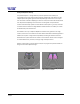
user manual TA-500 The Aspect Polyhorn™ Concept The patented Polyhorn™ design effectively solves the problem of the tendency for exponential horns to beam with increasing frequency. Dividing the multi-cellular horn into multiple tapered waveguides guarantees that the path length of each micro-horn is equal from the surface of the driver diaphragm to the horn mouth, and ensures that all frequencies from all parts of the diaphragm arrive at the horn mouth together.
user manual TA-500 • The TA-500 features approximately twice the horizontal and vertical dispersion as the narrower TA-880 and TA-890 products, making it more suitable for medium- and near-field applications in smaller rooms.
user manual TA-500 The Loudspeaker Management System (LMS) Concept Turbosound Loudspeaker Management Systems are more than just electronic crossovers. As well as steep slope active filters and high performance limiters, they provide full digital alignment of all components in the Aspect enclosures, to ensure a coherent acoustic output. They also incorporates a number of features which contribute to overall system reliability and ease of setting-up and use.
user manual TA-500 Power Amplifiers In addition to the Turbosound T-25 and T-45 model amplifiers recommended for use with Aspect systems, the following other power amplifier brands provide sufficient performance and mechanical compatibility to perform well with Aspect loudspeaker systems: • MC2 E series • Lab Gruppen FP series • Crest Pro series • QSC Powerlight II series Digital Controllers In addition to the Turbosound LMS-D24 and LMS-D26 loudspeaker management systems, the following digital cro
user manual TA-500 Neodymium magnets are used throughout all drive units. This results in higher efficiency, less power compression and reduced overall weight. Low-mid frequency drivers are designed to be rear-facing in the enclosure, enabling the heatsink / phase plug to be placed in the air flow to aid cooling.
user manual TA-500 TA-500 Three-way Loudspeaker The TA-500 trapezoidal enclosure contains a Turboloaded neodymium 15" LF driver, a custom 10” MF driver on a Polyhorn™ device, and a custom HF driver on a Polyhorn™ device, covering a frequency range from 60Hz up to 18kHz (with DSP). The two Polyhorn™ devices are designed to generate an exceptionally smooth and accurately defined wavefront across a 50º horizontal by 25º vertical dispersion pattern, and over the entire mid and high frequency bands.
user manual TA-500 rigging system and integrated Class D amplifier module. TA-500H Horizontal Three-way Loudspeaker The TA-500H is a horizontally-orientated version of the TA-500 with the mid/high section rotated through 90° in order to maintain a 50° horizontal by 25° vertical dispersion pattern housed in a rectangular enclosure. TA-500HDP Self-powered Horizontal Three-way Loudspeaker A self-powered version of the TA-500H horizontal enclure with integrated Class D amplifier module.
user manual TA-500 B18 Subwoofer The B18 is a compact bandpass subwoofer designed to be used in a variety of installed sound system applications as well as portable sub-bass support for Aspect TA-500 enclosures. It consists of a high-excursion, 4” voice-coil, 18” LF driver in a bandpass birch plywood enclosure of modest dimensions. Speakon NL4 connectors are provided on the rear panel with special cable access bays that allow cabinets to be positioned against a wall when interconnected.
user manual TA-500 Transportation An optional WB-500 wheelboard is available which clips on to the front of the cabinet, allowing single units to be conveniently transported. These are designed to be stackable, so that when not in use they can be neatly stored without taking up unecessary floor space.
user manual TA-500 FLYING AND STACKING Overview The Aspect system flying hardware is specifically designed to take advantage of its precise horizontal directivity characteristics, as well as to allow a wide range of adjustment of the vertical angles between adjacent enclosures, and the overall vertical inclination of each column of enclosures. This means that arrays can easily be optimised to suit the coverage requirements of any situation.
user manual TA-500 Safety Notes on Rigging The Turbosound Aspect rigging system has been designed and constructed to a high standard of safety, and tested to the most demanding of specifications. In order to ensure the highest safety standards, the information following on the assembly and safe use of rigging accessories must be carefully understood and followed. Only use Turbosound recommended rigging accessories, which are specifically designed for their intended purpose.
user manual TA-500 Secondary Safeties All loudspeakers flown in theatres, studios or other places of work and entertainment must, in addition to the principle load bearing means of suspension, be provided with an independent, properly rated and securely attached secondary safety. Only steel wire ropes or steel chains of an approved construction and load rating may be used as secondary safeties. Plastic covered steel wire ropes are not permitted for use as secondary safeties.
user manual TA-500 When initially ratcheting a column of speakers it is good to bear in mind the expected angle of inclination so as to avoid ending up with too much of the strap left on the ratchet. This is important because the ratchet can only take three complete turns before it releases itself. WARNING: If a tilt strap is released suddenly, the column of enclosures may tend to swing violently forwards and care must be taken to avoid danger to persons in the vicinity.
user manual TA-500 Sample Certificate of Load Test TA-500 user manual Page 21
user manual TA-500 FLYING HARDWARE Aspect TA-500 Flying Systems To take full advantage of the very precise dispersion properties of the Aspect system, two types of rigging system have been developed: a fully-integrated touring flying system which allows clusters to be rigged quickly and easily with an absolute minumum of additional external hardware; an an external flying system designed for use in fixed installations. The flying systems are inherently safe, flexible and simple to use.
user manual TA-500 A. TA-500T TOURING FLYING SYSTEM Consists of fully-integrated rigging hardware used together with fixed angle flybars offering the ability to fly single columns, and two-wide and three-wide clusters up to a maximum total of nine enclosures.
user manual TA-500 The net weight of the bar is 21kg and the SWL is 380kg. TOP VIEW PICKUP POINT (NARROW) PICKUP POINT (WIDE AND SINGLE) TILT STRAP POINT ENCLOSURE LIFT POINT (WIDE) ENCLOSURE LIFT POINT (SINGLE) BOTTOM VIEW ENCLOSURE LIFT POINT (NARROW) Figure 1: FB-500T/2W Touring Two-wide Flybar Figure 2: Flybar Lifting Points and Dimensions Two columns of enclures can be flown from the FB-500T/2W flybar.
user manual TA-500 The following combinations are possible using the two-wide flybar.
user manual TA-500 FC-500 flying chains are load tested to 140kg. The inter-cabinet chain assembly is rated at 60kg. Two inter-cabinet chain sets plus one top chain set provides the facility for lifting a maximum of three rows of enclosures. FC-500T Long Flying Chain Net weight is 1kg (2.2lbs) FC-500T Standard Length Flying Chain Net weight is 1kg (2.2lbs) Inter-cabinet Link Net weight is 0.5kg (1.
user manual TA-500 TS-890 Tilting Straps 0.5m 4.5m The tilting strap, TS-890, is in two parts. The longer part is attached to the tilt strap point on the flying bar using the buckle at its end. The other part of the strap with the ratchet is hooked into the tilt strap point on the underside of the bottom enclosure. The free end is then threaded through the ratchet and the strap tightened to achieve the desired tilt.
user manual TA-500 Bolt Figure 3: Cabinet Integral Flygear Captive biscuit Bolt A retractable sliding bolt manufactured from high tensile steel which is used to connect the links to the cabinet for suspending the column and the rows below. Captive Biscuit A captive biscuit is included in the cabinet, retained by a spring-loaded ball bearing. The component is designed to tie the backs of the cabinets together, whilst allowing up to 21° of vertical angle between rows.
user manual TA-500 Connecting Flying Chains to the Cabinet The bolt slides back along its runner enabling the placing of the profile into the slot. The bolt is spring loaded to ensure that when in its closed position (as shown below) it is free from vibration and cannot be damaged.
user manual TA-500 Sliding the top chain profile into the slot The profile is positioned into the slot so that the ‘wings’ bear on the top of the integral flygear assembly.
user manual TA-500 Connection of additional rows If additional rows are required, (up to two additional rows can be accommodated) in the cluster, these are easily attached using the integral hardware and the inter-cabinet link chains. The enclosures are stacked on the ground in appropriate positions to allow easy lifting with the flybar. The inter-cabinet link chains are attached from the outside of the cabinets using a similar procedure to the top chain assembly.
user manual TA-500 The lower link must fit into the flygear in a specific way to ensure the reinforcing part bears on the flygear appropriately: the link must be inserted correctly. Make sure that when using the 21° position the link is fitted parallel to the cabinet side.
user manual TA-500 Figure 9: Biscuit slides into lower cabinet Attaching the Tilt Straps When all cabinets have been linked and the top chains attached, the tilt straps can now be attached. First attach the longer strap to the flybar by sliding the flat buckle into the tilt strap attachment point.
user manual TA-500 Lifting the column When ALL the chains have been connected and the biscuit has been interlocked, the column is ready for lifting. Using the appropriate lifting point on the flybar, attach the bridle and lift ensuring during the lifting process that the column lifts evenly.
user manual TA-500 TA-500 user manual Page 35
user manual TA-500 B.
user manual TA-500 Rigging Instructions STEP 1 - Set the boxes out on the floor with the sides touching. Remove the M10 blanking screws from the rear of the boxes at top and bottom as illustrated.
user manual TA-500 STEP 2 - Fit a 3-wide hinge brace to the top of the array and a 3-wide rear brace to the bottom of the array using the twelve M10 x 40mm hex screws provided and torque to 25Nm. The use of thread-locking compound is recommended (see Appendix). Fit an M10 eyebolt to the centre of the rear brace. STEP 3 – Fit the enclosure connector to the top of the array.
user manual TA-500 Locate the four M10 x 40mm hex screws from the fixings kit and insert these through the enclosure connector into the rigging points on the two outside cabinets, together with four M10 shakeproof washers. Use the four M10 x 35mm hex screws from the fixings kit to lock the enclosure connector to the rear brace together with four flat washers and four M10 nylock nuts. All fixings should be thread-locked and torqued to 25Nm.
user manual TA-500 STEP 4 – The array is now ready to pick up. Pickup points 234mm [9.2"] Two independent pick-up points are recommended, spaced approximately 430mm (16.9”) apart, using the front two eyebolts. The two rear eyebolts are provided as safety points. Ensure all components are assembled using lock-tight. The total cluster weight including rigging hardware is approximately 210 kgs (462 lbs).
user manual TA-500 Flying a single TA-500 cabinet using M10 eyebolts The simplest method of flying a TA-500 cabinet is with a pair of M10 shoulder eyebolts on the top, using a third eyebolt on the rear of the cabinet to tilt the cabinet. 1. Remove the two countersunk M10 screws located towards the front of the cabinet. 2. Replace these with M10 shoulder eyebolts with a minimum thread length of 20mm (3/4”) 3. Angle the cabinet as necessary using the third eyebolt position on the rear of the cabinet.
user manual TA-500 LMS SERIES LOUDSPEAKER MANAGEMENT SYSTEMS Introduction This section is provided with the aim of assisting sound engineers, installers and consultants to fully understand Turbosound Loudspeaker Management Systems, and to obtain the full benefit of their capabilities. The Turbosound LMS-D26 and LMS-D24 are recommended for use with Aspect loudspeaker systems, offering varying features and facilities depending on the specific application.
user manual TA-500 LMS-D24 AND D26 LOUDSPEAKER MANAGEMENT SYSTEMS Features • Minimal signal path design, providing exceptional audio quality with carefully optimised processing and high performance converters for a full >111dB dynamic range, 96kHz sampling rate and minimal filtering. Audio-grade capacitors are used in the analogue signal path. • Sonically superb ADC / DAC combination; a carefully matched pairing of the best devices from Burr Brown and Wolfson.
user manual TA-500 Front Panel Functions Channel Select buttons Store and Recall buttons Input Signal Indicators 2x 24 character LCD Limiter Indicators Parameter Edit Encoders Edit Parameter Select buttons Output Mute buttons Input Signal Indicators – A set of three pairs of LED’s indicate signal present, +4dBu and input clip for both channels. The signal present LED’s operate at approximately –40 dBu, giving a useful indication of even relatively low input signal levels.
user manual TA-500 Text display – preset, channel, parameter and status information is shown on the 2x 24character text display. In most screens the currently selected channel is displayed on the upper line and the edit parameter on the lower line. To simplify the display and enhance security, some parameters or parameter pages are omitted when not relevant. Parameter Knobs – three velocity sensitive parameter knobs are used to adjust parameters shown on the display.
user manual TA-500 Rear Panel Functions Network Card Secure Mode Switch Audio Input Connectors Power Inlet Serial Comms Port Audio Output Connectors Power Inlet – provides connection to a suitable mains electricity supply using the cable supplied. The controller has a switch mode power supply that is capable of operating with a nominal mains voltage of 80 to 240v, 50/60Hz without re-configuration.
user manual TA-500 Operating the LMS-D24 and D26 Starting up The unit will energise as soon as power is applied to the IEC inlet; there is no power switch. During the start up process the firmware application model number and version numbers are displayed and the outputs are muted until the unit has completed its internal checks.
user manual TA-500 Navigation and Viewing Parameters (Note: The LMS-D26 is shown in all the following screen shots; however the features and parameters apply equally to the LMS-D24) Many of the processing elements in each input and output path have features that may be controlled by the user, such as gain, frequency or limiter threshold. We call these adjustable features parameters. LMS-D26 In A Freq EQ1 100Hz Width 1.4Q b a a Gain 0.
user manual TA-500 Navigation The DSP parameters are organised by channel. The currently selected channel is shown in the top left hand corner of the display. You can navigate between the channels by pressing the channel buttons. Pressing the channel buttons will scroll through the channels, utilities and back to the default screen. When using a Preset that is stereo linked, the channel selection will reflect this. For example ‘1&4’ indicates outputs 1 and 4.
user manual TA-500 Presets The device contains a total of forty-five user and Factory Presets. The user cannot overwrite the basic mono, basic stereo or Factory Preset programs. Preset Recall To select an existing Preset, press the Recall Button so the indicator above it illuminates. Turn parameter knob A until the required Preset number is shown on the display. Factory presets are indicated by a box symbol appearing after the preset number. Press the Recall Button again to activate the Preset.
user manual TA-500 Preset Store To store the current Preset in a user location, press the Preset Store Button so the indicator above it illuminates. Turn the first parameter knob until the required Preset location number is show on the display. A Preset name of up to 12 characters in length can be entered using parameter knobs B and C. Pressing the Store Button again completes the process and stores the Preset. As with Preset Recall, pressing any other button cancels the operation.
user manual TA-500 DSP Processing Layout Input DSP block diagram Input A Input LED’s Input Gain Delay 4th Order HPF Low Shelf EQ Six Band PEQ High Shelf EQ Routing SUM - 6dB NB.
user manual TA-500 DSP processing Input Channels Gain LMS-D26 In A Gain 0.0dB a c b a Knob A: Gain, adjustable in 0.2dB steps from –80 dB to +20dB Delay LMS-D26 In A Delay 1.50ms a b c a Knob A: Delay, adjustable in variable steps from 0 to 400ms The delay parameter is adjustable in fine steps at low values; the adjustment becomes progressively coarser as the value increases.
user manual TA-500 High Pass Filter LMS-D26 In A Freq Shape HPF 20.0Hz LR24 a a b c b Knob A: Frequency, out (off), 10.0Hz to 25.6kHz in variable steps Knob B: high pass filter type System high pass filtering is provided for the input signal. This is the preferred location for high pass filtering as it affects all outputs and can therefore improve inter-band phase relationships. Filter type is selectable from Butterworth, Bessel, Linkwitz-Riley and Hardman.
user manual TA-500 Parametric Equalisation Eight sections of equalisation are provided, two shelving filters and six fully variable parametric sections. High and Low shelving filters LMS-D26 In A Freq EQ1 100Hz Slope 12dB c b a a Gain 0.0dB b c Knob A: Frequency, 10.0Hz to 25.6kHz in variable steps Knob B: Slope, 6 to 12dB / octave in 1dB steps Knob C: Gain, +/-15dB in 0.2dB steps The frequency is specified as point where the filter deviates by 3dB from the gain value.
user manual TA-500 Output Channels Gain and Polarity LMS-D26 Out1 Gain 0.0dB Pol Rev a a c b b Knob A: Gain, adjustable in 0.2dB steps from –80 dB to +20dB Knob B: Polarity, selectable, normal or reversed with reference to other outputs Delay LMS-D26 Out1 Delay 1.50ms a b c a Knob A: Adjustable in variable steps from 0 to 80ms As for input delay, velocity sensitive Parameter Knobs provide finer adjustment at low levels and rapid selection of higher values.
user manual TA-500 High and Low Pass Filters LMS-D26 Out1 Freq LPF 2.50k Shape LR24 a a b c b Knob A: Frequency, <> Knob B: high pass filter type Filter type is selectable from Butterworth, Bessel, Linkwitz-Riley and Hardman. Filter slopes of up to 8th order or 48dB / octave are provided. Not all filter types are available in all slopes. For example 18dB / octave Linkwitz-Riley filters do not exist.
user manual TA-500 Parametric Equalisation Eight sections of equalisation are provided in a similar format to the input channel equalisation; two shelving filters and six parametric. LMS-D26 Out1 Freq EQ>- 100Hz Slope 12dB a a Gain 0.0dB c b b c Knob A: Frequency, 10.0Hz to 25.6kHz in variable steps Knob B: Slope, 6 to 12dB / octave in 1dB steps Knob C: Gain, +/-15dB in 0.2dB steps The frequency is specified as point where the filter deviates by 3dB from the gain value.
user manual TA-500 Limiters LMS-D26 Out1 Thresh LIM 4.0dB a c b a Knob A: Threshold, -40dBu to 20dBu in 0.2dB steps A high performance, low distortion limiter is provided on each output. Threshold is user adjustable; all other parameters are carefully calculated dependant on configuration to provide clean and effective control of signal dynamics.
user manual TA-500 Utilities Utility functions Two utility functions are provided to adjust screen contrast and the display units used for parametric equalisation bandwidth. The device automatically adjusts for the variations in display contrast as the temperature of the LCD changes. The screen contrast utility control sets the base contrast of the screen and also allows optimization for a given viewing angle.
user manual TA-500 T-25 AND T-45 HIGH EFFICIENCY AUDIO POWER AMPLIFIERS General Features & Facilities The T-25 and T-45 are highly efficient, lightweight, rugged high power amplifiers, with many original features developed to meet the requirements of modern professional sound reinforcement, for both touring and fixed installations. They have been designed with audio quality ranking equal first alongside utility and ruggedness.
user manual TA-500 Front Panel Functions T-25 Ch. A Ch.B • Mains power rocker switch – applies AC mains power to the amplifier. • Mains power LED – illuminates when AC power is applied to the amplifier. • Gain – rotary control which allows the gain of the channel to be adjusted. • Signal – blue LED indicates signal presence, active from a minimum output level of 10 watts. TA-500 user manual Page 62 • -3dB – yellow LED is active when the signal is 3dB below the limiting level.
user manual TA-500 Front Panel Functions T-45 Ch. A Ch.B • Mains power rocker switch – applies AC mains power to the amplifier. • Mains power LED – illuminates when AC power is applied to the amplifier. • Gain – rotary control which allows the gain of the channel to be adjusted. • Signal – blue LED indicates signal presence, active from a minimum output level of 10 watts. • -3dB – yellow LED is active when the signal is 3dB below the limiting level.
user manual TA-500 Mechanical Installation When supplied as part of the AMP-890.2 system rack, the amplifiers are pre-installed. If an amplifier is removed from the rack for any reason, it is important to re-install it correctly. The amplifiers must be supported at the front and rear, as originally supplied. Failure to support it adequately may eventually result in vibration-induced metal fatigue of the rack mounting ears and such damage will not be covered by the warranty.
user manual TA-500 Voltage Setting Your models will be set up at the factory for correct operation on your local voltage supply. No further adjustment is necessary. Voltage Range The minimum supply voltage over which the amplifier will operate is 180V for the 220-240V range, and 90V for the 110-120V range. Naturally, maximum power output will be reduced accordingly from the published ratings.
user manual TA-500 of performance may be experienced if connected to unbalanced sources. If it is unavoidable, however, the following wiring convention should be used.
user manual TA-500 Setting higher gain does not change the maximum available power but changes the level of signal input to achieve maximum power. In any case, provided that the input signal is less than 20dBu/7.7V, the built in limiter circuit will prevent distortion within the amplifier. The gain should be set to match the signal from the source, e.g. mixer, controller, or equaliser.
user manual TA-500 Long Speaker Lines Whenever loudspeakers are connected to power amplifiers by long cables (above 20'/6m), there is invariably an increased risk of high frequency instability. It is aggravated by the combination of RF pickup in unshielded cables acting as aerials, and multiple complex reactances in the cable and loudspeakers.
user manual TA-500 APPENDIX A: TECHNICAL SPECIFICATIONS TA-500 TA-500t TA-500H TA-500HM Dimensions 977 x 574 x 498 977 x 574 x 498 551 x 983 x 498 551 x 574 x 498 mm (inches) (38.5 x 22.6 x 19.6) (38.5 x 22.6 x 19.6) (22.6 x 55.1 x 30.3) (21.7 x 22.6 x 19.6) Net weight 52kg (114.4lbs) 57kg (125.4lbs) 52kg (114.4lbs) 37kg (81.
user manual TA-500 TA-500DP TA-500tDP TA-500HDP Dimensions 977 x 574 x 498 977 x 574 x 498 551 x 983 x 498 mm (inches) (38.5 x 22.6 x 19.6) (38.5 x 22.6 x 19.6) (22.6 x 55.1 x 30.3) Net weight 54kg (123.2lbs) 59kg (130lbs) 54kg (118.
user manual TA-500 APPENDIX B: SPARE PARTS LIST Stock Code Model Description 07A0255 FG-500T Flygear assembly (2 sides inc bolts, springs, gaskets and fixings) 07E008 BG-890 Bolt guide plate 07E015 BS-890 Captive biscuit 07B075 SK-500 Screw kit for flygear (replace after service or inspection) LS1021/2 LS-1021.
user manual TA-500 APPENDIX C: WARRANTY All products in this manual are warranted by Turbosound Limited to the original end-user purchaser against defects in workmanship and materials used in its manufacture for a period of one year on electronics products and two years on loudspeaker products from date of shipment to the end user. Faults arising from misuse, unauthorised modifications or accidents are not covered by this warranty. No other warranty is expressed or implied.
user manual TA-500 Turbosound Limited Star Road Partridge Green West Sussex RH13 8RY United Kingdom TA-500 user manual Page 73