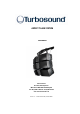
ASPECT TA-890 SYSTEM USER MANUAL Turbosound Ltd. Star Road, Partridge Green West Sussex RH13 8RY United Kingdom Tel: +44 (0)1403 711447 Fax: +44 (0)1403 710155 web: www.turbosound.com Issue 1.
user manual TA-890 Contents EC Declaration of Conformity........................................................................................................................ 6 Introduction .................................................................................................................................................... 7 Turbosound Aspect System Concepts ..................................................................................................... 7 The Turbosound Polyhorn™.....
user manual TA-890 Setting up a Venue - Overview............................................................................................................... 17 Running Turbosound GigMate™ / EASE Focus for the first time: ....................................................... 18 Designing a system ................................................................................................................................. 20 Changing the system .......................................................
user manual TA-890 Introduction ............................................................................................................................................. 47 General features & facilities.................................................................................................................... 47 Unpacking ................................................................................................................................................ 47 Mechanical Installation ..
user manual TA-890 Utility functions ....................................................................................................................................... 69 Rear Panel Functions............................................................................................................................... 70 AMP-890 Aspect System Amplification Rack ............................................................................................. 71 Racking, Cables and Connections .............
user manual TA-890 EC DECLARATION OF CONFORMITY Manufacturer Turbosound Ltd Star Road, Partridge Green, West Sussex, RH13 8RY, UK Products T-25 Power Amplifier T-45 Power Amplifier LMS-D6 Loudspeaker Management System LMS-D24 & LMS-D26 Loudspeaker Management System Standards Safety EN60065:2003 Relevant Specifications used as basis for tests EN66103-1:1996 EN55103-2:1996 Category Professional apparatus for use in Commercial Light Industrial and controlled EMC environments.
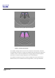
user manual TA-890 INTRODUCTION Turbosound Aspect System Concepts The TA-890 system is a modular point source loudspeaker system designed to deliver extremely high fidelity audio. The system is easily scaleable from large and medium scale concert touring applications to small clubs and events. The Aspect system concept centres around the exceptional directivity of the patented Polyhorn™ devices employed in the high frequency and high-mid frequency sections of the mid/high enclosure.
user manual TA-890 Conventional HF horns produce destructive interference Poyhorn™ - smoothly curved wavefront The TA-890H mid-high enclosure forms the main component of flown clusters, and can be orientated either horizontally or vertically (the mid/high section pictured above is square and rotatable) in order to match venue specifics such as rigging height and audience sightline restrictions. It can also be usefully employed as a front or side fill cabinet.
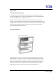
user manual TA-890 ASPECT TA-890 TURNKEY SYSTEM CONCEPT Aspect is available as an integrated audio system package, comprising loudspeakers with integral flying hardware, amplifier racks and all necessary drive and control equipment in an extremely compact and manageable form. In addition, the system has been designed to truck pack efficiently and handle easily.
user manual TA-890 The Loudspeaker Management System (LMS) Concept Turbosound Loudspeaker Management Systems are more than just electronic crossovers. They provide full digital alignment of all components in the Aspect enclosures, to ensure coherent acoustic output. They also incorporates a number of features which contribute to overall system reliability and ease of setting-up.
user manual TA-890 • MC2 E series • Lab Gruppen FP series • Crest Pro series • QSC Powerlight II series Digital Controllers In addition to the Turbosound LMS-D6 and LMS-D26 loudspeaker management systems, the following digital crossovers have been tested and are recommended for use with Aspect systems: • BSS FDS366 • XTA DP224, DP226 and DP428 Aspect Loudspeaker Components All the drive units have been designed in-house specifically for the Aspect system and are manufactured exclusively for Tu
user manual TA-890 TSW-218 Subwoofer The TSW-218 is designed to cover the sub and low frequency ranges from 25Hz to 100Hz, and can be used as part of a 5-way Aspect system in order to reinforce sub-bass frequencies. It utilises two custom designed neodymium 18” drivers loaded with TurboBass™ devices. The proprietary loading technique and horn flare design produces significant mutual coupling between adjacent enclosures, resulting in sensitivity gains of up to 110dB with eight units coupled.
user manual TA-890 It includes a hinged rear access door, integral multi-way speaker cable, removable wheel board, ergonomically placed flush handles, weatherised beech plywood construction and optimised truck-pack dimensions. The TA-890H enclosure is exactly the same size as, and of very similar weight to, the TA-890L.
user manual TA-890 Transportation TA-890 cabinets include a removable wheelboard which clips to the front of the cabinet, allowing single units to be conveniently transported. These are designed to be stackable, so that when not in use they can be neatly stored without taking up floor space. The wheelboards will fit both mid-high and low frequency cabinets.
user manual TA-890 Aspect Flying Systems To take full advantage of the very precise dispersion properties of the Aspect system, an integral rigging system has been developed. The flying system is inherently safe, flexible and simple to use, and even though it is integral to the box, it may be quickly and easily removed for safety testing.
user manual TA-890 FLYING AND STACKING Overview The Aspect system flying hardware is specifically designed to take advantage of the precise horizontal directivity characteristics, as well as allow a wide range of adjustment of the vertical angles between adjacent enclosures, and the overall vertical inclination of each column of enclosures. This means that arrays can easily be optimised to suit the coverage requirements of any situation.
user manual TA-890 GIGMATE™ ACOUSTIC SIMULATION While the Aspect System is remarkably intuitive in terms of building arrays and aiming them, and requires no theoretical calculations in order to achieve optimum coverage of a room or audience space due to its inherent ‘point-and-shoot’ nature, there may well be situations where some prior knowledge of a venue can save time in setting up and configuring the PA.
user manual TA-890 Running Turbosound GigMate™ / EASE Focus for the first time: When you first start the program you must set the system file that it is to use. The installation files include two Turbosound Aspect System files as shown below: Select the Touring version cabinets. You will now be presented with the GigMate™ main screen.
user manual TA-890 The screen is split into four main areas: System Setup The left hand side of the screen is where you define the system, auditorium and project. Tabs On the bottom of this window allow you to toggle between modes. Mapping Properties This is the main window which will display the system as configured in the System Setup window along with the audience areas and mappings.
user manual TA-890 Designing a system To design a system begin by defining the venue/audience areas by clicking on the “Audience Area” tab in the bottom left of the screen. Within this window you can edit or remove existing audience areas, and create new ones. There are two methods of defining an audience area. In either case you must define the X1/Y1 coordinate of the start of the area, you can then either enter the X2/Y2 points or its length and angle.
user manual TA-890 Now select the number of cabinets deep that you wish to hang or stack from the “Box Count” drop-down menu. Trim height, or PA wing height can now be set in the “Position” field. If a mix of Low and High cabinets are to be used then select in the “Cabinet” window the type and location in the array of each box. The angle between cabinets can now be set in the “Angle” list. Each cabinet has an aiming line that can be used to determine the centre of each cabinet’s dispersion.
user manual TA-890 Now that the general design has been established the system performance must be mapped. At the top of the main window there is an “SPL Mapping” checkbox. This will map the system output at the frequency and bandwidth selected in the adjacent dropdown boxes. For most applications a one-third octave mapping gives realistic and useful data.
user manual TA-890 The Audience Area graph at the bottom of the window shows the SPL, as specified in the SPL Mapping lists, on the selected Audience Area. The selected area is highlighted in the main window and the graph is repeated onto each area. Selecting the “Combined Level View” tab will show the SPL across all areas simultaneously. Now that the system is mapped, the inter-cabinet angles or row attenuation may be trimmed to provide the smoothest coverage.
user manual TA-890 Two typical examples are shown here.
user manual TA-890 Safety Notes on Rigging The Turbosound TA-880 system has been designed and constructed to a high standard of safety, and tested to the most demanding of specifications with a safety factor of 13:1. Always wear protective headwear, footwear and eye protection in accordance with local regulations.
user manual TA-890 Sample Certificate of Load Test TA-890 user manual Page 26
user manual TA-890 Flying Hardware The ‘A’ system flying bars consist as follows: • Single bar – supports a vertical column of cabinets up to 8 deep. • Twin bar – supports two vertical columns up to 8 deep.
user manual TA-890 Figure 1. Single A-System Flybar FB-890/1A The single flybar is fabricated from box steel section with integral lifting point, safety point, enclosure suspension tabs and tilting strap pick-up point, designed to fly a single box or vertical column of boxes up to eight deep. The bar can be flown from a single one-tonne motor.
user manual TA-890 Figure 2. Double A-System Flybar FB-890/2A A fixed angle double bar fabricated from box steel section and designed to fly two vertical columns of cabinets up to eight deep per column. It provides alternative cabinet suspension tabs and tilt strap points for narrow or wide configurations (when flying more than four boxes deep the wide configuration allows for the additional amount of kelp required), plus lifting points and safety points.
user manual TA-890 Figue 3. Triple ‘A’ System Flybar FB-890A/3W A fixed angle triple bar designed to fly three vertical columns of cabinets in the ‘A’ or horizontal orientation. It provides both narrow and wide configuration settings in order to accommodate deep arrays of up to eight cabinets. The FB-890A/3W can be flown using either the single lift points or the chain bridle lift points. The net weight of the bar is 80kg.
user manual TA-890 FC-890 Flying Chains An adjustable length flying chain, consisting of a top hook, chain with adjusting choke, and a cabinet link, is used to connect the cabinets to the flybars. The top chain from the flybar to the first cabinet can be adjusted to gain more height on the system and also improve the looks. Alternatively if you are flying four or more cabinets deep with a lot of kelp it is good to give the top chain some additional length as this makes racheting easier.
user manual TA-890 Three-wide hang using MB-890, EB-890, FB-890/2A and FB-890/1A Consists of a FB-890/1A single bar and a FB-890/2A double bar, coupled with a left or right hand side FB-890MB motherbeam and one MBE-890 left or right side extender beam. The geometry of the system ensures that the optimum 25° horizontal angle is maintained between columns. This configuration can be bridled from a single one-tonne point when flying uip to three cabinets deep.
user manual TA-890 Four-wide hang using MB-890 and FB-890/2A Consists of two FB-890/2A double bars, coupled with an MB-890 motherbeam. The geometry of the system ensures that the optimum 25° horizontal angle is maintained between columns. The diagrams below illustrate both narrow and wide flybar settings. The flybar has two lifting points. These can be bridled from a single one-tonne point when flying cabinets three deep or less on the narrow setting.
user manual TA-890 Integral Flying Hardware Aspect cabinets are flown and connected in vertical columns by means of the integral flygear that is rebated into the cabinet sides. In this way the load of the cluster is taken entirely through the steelwork and not through the box. It essentially consists of a moveable drop link that engages into a receptacle in the cabinet below with a choice of inter-cabinet angles.
user manual TA-890 1. Drop Link A retractable sliding mechanism that extends downwards to engage in the flygear of the cabinet below. It is backed with an anti-vibration spring. 2. Swing Latch A spring-loaded lever that secures the flying chain or the drop link of the cabinet above. Pull back to locate the drop link, release to engage.
user manual TA-890 Setting Vertical Angles – ‘A’ System The position of the tilt index determines the distance between cabinets, and hence the vertical angle when the column is lifted. There are four possible discrete increments.
user manual TA-890 Attaching the Tilt Straps When all cabinets have been linked and the top chains attached, the tilt straps can now be attached. First attach the longer strap to the flybar by sliding the flat buckle into the tilt strap attachment point. Slide the flat buckle on the shorter strap into the tilt strap point on the bottom of the cabinet, insert the free end of the strap through the centre of the ratchet spindle, and pull to apply some tension before ratcheting the column.
user manual TA-890 Turbobass Directivity The Aspect series TA-890L bass bin and the TSW-218 subwoofer are “Turbobass” devices, comprising horn-loaded drivers. Whilst this horn loading does aid in tuning the device and adding some sensitivity, the relationship between horn length and the bandwidth covered by the enclosures means that each source is effectively an omni-directional point source.
user manual TA-890 Tall, thin bass stacks work best, preferably in blocks of six or eight bins high by two wide. When space permits use two or three of these blocks, placing the onstage block flush with and parallel to the stage, with a second and additional identical offstage blocks slightly separated from the first and angled outwards by 40°. Stacking bass cabinets in a line in front of the stage will produce narrower dispersion in the horizontal plane, while giving wide vertical dispersion.
user manual TA-890 The typical Left to Right problem One of the most common problems on large scale events results from the relationship between the left and right bass stacks. Due to the difference in distance and arrival time at any point between two point sources, in this case bass arrays, there will inevitably be some positive addition and some negative cancellation between sources.
user manual TA-890 Whilst several manufacturers have attempted to solve this using DSP based systems at present there is not a working solution in the market. In theory by splitting the LF energy into several bands and then spacing the left/right stacks differently depending on frequency this effect can be solved or at least minimised. However, due to the available space within a venue and the maximum roll-off available from common crossover systems we consider this to be neither effective or practical.
user manual TA-890 The result here is tight horizontal pattern control with two side lobes. This is a common application of subwoofers used in the field. There are however, several points to notice. Firstly, almost as much energy is produced behind the array as in front of it, which can create problems on stage or on multiple-staged outdoor events. At the same time this will always provide a tightly controlled beam, providing focused low end energy which will drop off sharply outside the coverage area.
user manual TA-890 Bessel Array In the above example five bass bins are again spaced ¼ of a wavelength apart. However in this example the outside two are reduced in gain by 3dB. The inside pair are out of phase while the middle unit is in phase. This is known as a Bessel array, and will create the smoothest horizontal coverage possible at a given frequency.
user manual TA-890 End firing array Under today’s market conditions it is often necessary to abide by strict environmental considerations. This is particularly pertinent at open air festival sites where there are multiple stages and external noise limits. Aspect TA-890H mid/high boxes are uniquely positioned in a line array dominated marketplace to deal with this problem by allowing the user to tailor the horizontal and vertical dispersion to the desired coverage area.
user manual TA-890 Summing up Generally left and right bass stack are deployed. These should be kept as far apart as possible, and stacked high or fanned to minimise beaming. Toeing these out can hep to reduce cancellation between left and right stacks. On large sites or in situations where left to right cancellation is particularly bad, a fan shaped array will solve the problem. When possible smoother coverage can be obtained by using additional processing to create a Bessel array.
user manual TA-890 Ground stacking In certain situations, indoors or outdoors, it may not be possible to fly any part of the system. In this case, the same general rules apply as for flown arrays. High packs should be kept well above head-height and angled carefully for even coverage. The integrated ‘A’ system flygear permits convenient ground stacking of both 890H mid-highs and 890L low cabinets.
user manual TA-890 LMS SERIES LOUDSPEAKER MANAGEMENT SYSTEMS Introduction This section is provided with the aim of assisting sound engineers, installers and consultants to fully understand Turbosound Loudspeaker Management Systems, and to obtain the full benefit of their capabilities. The LMS-D6 and LMS-D26 are dedicated Loudspeaker Management Systems, specially configured for Turbosound's Aspect Systems, and to be used in conjunction with Turbosound AMP-890 amplifier racks.
user manual TA-890 LMS-D6 Front Panel Functions 5 4 LMS-D6 3 MENU ENTER 6 FREQ 9 'Q' GAIN 10 A B 11 1 CLIP TQ-440 GAIN 8 3 LIM -3 MUTE -24 4 5 LIM LIM -3 MUTE -24 -3 MUTE -24 6 LIM -3 -3 -24 -24 OUT DIGITAL LOUDSPEAKER MANAGEMENT SYSTEM 1 2 LIM -6 -24 BYPASS 12 GAIN 7 GAIN GAIN GAIN GAIN GAIN GAIN 2 1. LCD Display - Shows menu options, output information and adjustment parameters. 2.
user manual TA-890 LMS-D6 Rear Panel Functions RS232 DATA INPUT WARNING / AVIS OUTPUT 6 OUTPUT 5 OUTPUT 4 OUTPUT 3 OUTPUT 2 OUTPUT 1 INPUT B INPUT A DO NOT EXP OSE TO RA IN OR MOIST URE THIS EQUIPMENT M UST BE EARTHED SHOCK HAZARD – DO NOT REMOVE COVER S RISQUE DE CHOC ELECTRIQUE - NE PAS OUVRIR PROTECTION AGAINST FIRE REPLACE ONLY WITH THE SAME TYPE T1A, 250V FUSE 1 2 3 PIN1=SHIELD PIN2=HOT PIN3=COLD CUSTOM MADE FOR TURBOSOUND IN THE UK BY XTA ELECTRONICS 4 5 1. Power Switch. 2.
user manual TA-890 Voltage Setting The LMS-D6 is provided with an auto-seeking power supply, and therefore requires no external adjustment for correct operation with international AC line voltages ranging from 60 to 250 volts. Safety Earthing The green/yellow wire of mains cord must always be connected to the electrical installation's Safety Earth or Ground. It is essential for personal safety, as well as proper operation of the unit.
user manual TA-890 Audio Connections The LMS-D6 audio inputs are RFI filtered and electronically balanced. The outputs are electronically balanced and fully floating. Overall, the unit is designed to operate at any signal levels ranging -10dBu up to +20dBu. The outputs will drive into loads of 600 Ohms or greater and both inputs and outputs are intended to be 'fuss free', regardless of an installation's complexity.
user manual TA-890 LMS-D24 AND D26 LOUDSPEAKER MANAGEMENT SYSTEMS Features • Minimal signal path design, providing exceptional audio quality with carefully optimised processing and high performance converters for a full >111dB dynamic range, 96kHz sampling rate and minimal filtering. Audio-grade capacitors are used in the analogue signal path. • Sonically superb ADC / DAC combination; a carefully matched pairing of the best devices from Burr Brown and Wolfson.
user manual TA-890 Front Panel Functions Channel Select buttons Store and Recall buttons Input Signal Indicators 2x 24 character LCD Limiter Indicators Parameter Edit Encoders Edit Parameter Select buttons Output Mute buttons Input Signal Indicators – A set of three pairs of LED’s indicate signal present, +4dBu and input clip for both channels. The signal present LED’s operate at approximately –40 dBu, giving a useful indication of even relatively low input signal levels.
user manual TA-890 Edit Select Buttons – the currently selected edit parameter is displayed on the bottom left corner of the LCD. Pressing the edit select buttons moves through the available parameters for the current input or output. Text display – preset, channel, parameter and status information is shown on the 2x 24character text display. In most screens the currently selected channel is displayed on the upper line and the edit parameter on the lower line.
user manual TA-890 Rear Panel Functions Expansion Port Power Inlet Secure Mode Switch Audio Input Connectors Serial Comms Port Audio Output Connectors Power Inlet – provides connection to a suitable mains electricity supply using the cable supplied. The controller has a switch mode power supply that is capable of operating with a nominal mains voltage of 80 to 240v, 50/60Hz without re-configuration. Network expansion port – where a future network card can be fitted.
user manual TA-890 OPERATING THE LMS-D24 AND D26 Starting up The unit will energise as soon as power is applied to the IEC inlet; there is no power switch. During the start up process the firmware application model number and version numbers are displayed and the outputs are muted until the unit has completed its internal checks.
user manual TA-890 Navigation and Viewing Parameters (Note: The LMS-D26 is shown in all the following screen shots; however the features and parameters apply equally to the LMS-D24) Many of the processing elements in each input and output path have features that may be controlled by the user, such as gain, frequency or limiter threshold. We call these adjustable features parameters. LMS-D26 In A Freq EQ1 100Hz Width 1.4Q b a a Gain 0.
user manual TA-890 Navigation The DSP parameters are organised by channel. The currently selected channel is shown in the top left hand corner of the display. You can navigate between the channels by pressing the channel buttons. Pressing the channel buttons will scroll through the channels, utilities and back to the default screen. When using a Preset that is stereo linked, the channel selection will reflect this. For example ‘1&4’ indicates outputs 1 and 4.
user manual TA-890 PRESETS The device contains a total of forty-five user and Factory Presets. The user cannot overwrite the basic mono, basic stereo or Factory Preset programs. Preset Recall To select an existing Preset, press the Recall Button so the indicator above it illuminates. Turn parameter knob A until the required Preset number is shown on the display. Factory presets are indicated by a box symbol appearing after the preset number. Press the Recall Button again to activate the Preset.
user manual TA-890 Preset Store To store the current Preset in a user location, press the Preset Store Button so the indicator above it illuminates. Turn the first parameter knob until the required Preset location number is show on the display. A Preset name of up to 12 characters in length can be entered using parameter knobs B and C. Pressing the Store Button again completes the process and stores the Preset. As with Preset Recall, pressing any other button cancels the operation.
user manual TA-890 DSP PROCESSING LAYOUT Input DSP block diagram Input A Input LED’s Input Gain Delay 4th Order HPF Low Shelf EQ Six Band PEQ High Shelf EQ Routing SUM - 6dB NB.
user manual TA-890 DSP PROCESSING Input Channels GAIN LMS-D26 In A Gain 0.0dB a c b a Knob A: Gain, adjustable in 0.2dB steps from –80 dB to +20dB DELAY LMS-D26 In A Delay 1.50ms a b c a Knob A: Delay, adjustable in variable steps from 0 to 400ms The delay parameter is adjustable in fine steps at low values; the adjustment becomes progressively coarser as the value increases.
user manual TA-890 HIGH PASS FILTER LMS-D26 In A Freq Shape HPF 20.0Hz LR24 a a b c b Knob A: Frequency, out (off), 10.0Hz to 25.6kHz in variable steps Knob B: high pass filter type System high pass filtering is provided for the input signal. This is the preferred location for high pass filtering as it affects all outputs and can therefore improve inter-band phase relationships. Filter type is selectable from Butterworth, Bessel, Linkwitz-Riley and Hardman.
user manual TA-890 Parametric Equalisation Eight sections of equalisation are provided, two shelving filters and six fully variable parametric sections. High and Low shelving filters LMS-D26 In A Freq EQ1 100Hz Slope 12dB c b a a Gain 0.0dB b c Knob A: Frequency, 10.0Hz to 25.6kHz in variable steps Knob B: Slope, 6 to 12dB / octave in 1dB steps Knob C: Gain, +/-15dB in 0.2dB steps The frequency is specified as point where the filter deviates by 3dB from the gain value.
user manual TA-890 OUTPUT CHANNELS Gain and Polarity LMS-D26 Out1 Gain 0.0dB Pol Rev a a c b b Knob A: Gain, adjustable in 0.2dB steps from –80 dB to +20dB Knob B: Polarity, selectable, normal or reversed with reference to other outputs Delay LMS-D26 Out1 Delay 1.50ms a b c a Knob A: Adjustable in variable steps from 0 to 80ms As for input delay, velocity sensitive Parameter Knobs provide finer adjustment at low levels and rapid selection of higher values.
user manual TA-890 High and Low Pass Filters LMS-D26 Out1 Freq LPF 2.50k Shape LR24 a a b c b Knob A: Frequency, <> Knob B: high pass filter type Filter type is selectable from Butterworth, Bessel, Linkwitz-Riley and Hardman. Filter slopes of up to 8th order or 48dB / octave are provided. Not all filter types are available in all slopes. For example 18dB / octave Linkwitz-Riley filters do not exist.
user manual TA-890 Parametric Equalisation Eight sections of equalisation are provided in a similar format to the input channel equalisation; two shelving filters and six parametric. LMS-D26 Out1 Freq EQ>- 100Hz Slope 12dB a a Gain 0.0dB c b b c Knob A: Frequency, 10.0Hz to 25.6kHz in variable steps Knob B: Slope, 6 to 12dB / octave in 1dB steps Knob C: Gain, +/-15dB in 0.2dB steps The frequency is specified as point where the filter deviates by 3dB from the gain value.
user manual TA-890 Q adjustable from 14.2 to 0.2 in variable steps Knob C, Gain, +/-15dB in 0.2dB steps Limiters LMS-D26 Out1 Thresh LIM 4.0dB a c b a Knob A: Threshold, -40dBu to 20dBu in 0.2dB steps A high performance, low distortion limiter is provided on each output. Threshold is user adjustable; all other parameters are carefully calculated dependant on configuration to provide clean and effective control of signal dynamics.
user manual TA-890 UTILITIES Utility functions Two utility functions are provided to adjust screen contrast and the display units used for parametric equalisation bandwidth. The device automatically adjusts for the variations in display contrast as the temperature of the LCD changes. The screen contrast utility control sets the base contrast of the screen and also allows optimization for a given viewing angle.
user manual TA-890 Rear Panel Functions Expansion Port Power Inlet Secure Mode Switch Audio Input Connectors Serial Comms Port Audio Output Connectors Power Inlet – provides connection to a suitable mains electricity supply using the cable supplied. The controller has a switch mode power supply that is capable of operating with a nominal mains voltage of 80 to 240v, 50/60Hz without re-configuration. Network expansion port – where a future network card can be fitted.
user manual TA-890 AMP-890 ASPECT SYSTEM AMPLIFICATION RACK Ch.A Ch.B Ch.A Ch.B Ch.A Ch.B Ch.A Ch.B Ch.A Ch.B INPUT OR LINK SOCAPEX SOCAPEX LOW OUTPUTS CH 1A CH 1B CH 2A HIGH OUTPU TS CH 2B CH 1 CH 2 Racking, Cables and Connections The AMP-890 Aspect amplification system comprises a complete amplifier rack, flightcase and cabling system which is adaptable to the varying requirements of modern concert touring.
user manual TA-890 Options The rack is supplied fitted with five amplifiers as standard. The two top amplifiers are T-25 models, and power the high frequency and high-mid frequency sections respectively. Three mid-high cabinets will normally be powered from each channel, although it is possible to run up to four cabinets for some extreme applications. The remaining three amplifiers are all T-45 models and power the low-mid frequency and low frequency sections.
user manual TA-890 Figure 1.
user manual TA-890 Figure 2. Mid-High Outputs SOCAPEX PIN NO. CH2 NL8 PIN NO. SOCAPEX PIN NO. CH2 CH1 NL4FC HF+ HF - 01 03 4+ 4- HF+ HF - CHANNEL 1 HF CH2 02 04 4+ 4- 06 08 3+ 3- 13 14 15 16 2+ 2- CHANNEL 2 HF CH1 CH2 CH1 NL4FC NL4FC HM+ HM - 05 07 3+ 3- HM+ HM - CHANNEL 1 HM CH2 NL8 PIN NO. CH1 NL4FC CHANNEL 2 HM CH1 CH2 NL4FC LM+ LM - 09 10 11 12 CH1 NL4FC LM+ LM - 2+ 2- CHANNEL 1 LM CHANNEL 2 LM Figure 3. Bass Outputs SOCAPEX PIN O N. CH2 NL4 PIN N O.
user manual TA-890 Break-out Cables – NL4 bass NL4 PIN NO. SOCAPEX PIN N O.
user manual TA-890 Break-out cables – NL8 mid-high SOCAPEX PIN O. N 11 NL8 PIN N O. LOW/MIDLOW/MID+ SOCAPEX PIN O. N 15 22+ 3- NL8 PIN N O.
user manual TA-890 Mains Connections Incoming mains power may be connected by one of a variety of C Form connectors, depending on the power system specified when the rack was ordered. Typical supply configurations are as follows: 110 V star-wired (3 phase) 110 V parallel (1 phase) 220/240 V (3 phase) 220/240 V (1 phase) The mains power wiring utilises Wago distribution blocks with spring-loaded screwless connectors.
user manual TA-890 T-25 AND T-45 HIGH EFFICIENCY AUDIO POWER AMPLIFIERS General Features & Facilities The T-25 and T-45 are highly efficient, lightweight, rugged high power amplifiers, with many original features developed to meet the requirements of modern professional sound reinforcement, for both touring and fixed installations. They have been designed with audio quality ranking equal first alongside utility and ruggedness.
user manual TA-890 Front Panel Functions T-25 Ch. A Ch.B • Mains power rocker switch – applies AC mains power to the amplifier. • Mains power LED – illuminates when AC power is applied to the amplifier. • Gain – rotary control which allows the gain of the channel to be adjusted. • Signal – blue LED indicates signal presence, active from a minimum output level of 10 watts. • -3dB – yellow LED is active when the signal is 3dB below the limiting level.
user manual TA-890 Front Panel Functions T-45 Ch. A Ch.B • Mains power rocker switch – applies AC mains power to the amplifier. • Mains power LED – illuminates when AC power is applied to the amplifier. • Gain – rotary control which allows the gain of the channel to be adjusted. • Signal – blue LED indicates signal presence, active from a minimum output level of 10 watts. TA-890 user manual Page 80 • -3dB – yellow LED is active when the signal is 3dB below the limiting level.
user manual TA-890 Mechanical Installation When supplied as part of the AMP-890.2 system rack, the amplifiers are pre-installed. If an amplifier is removed from the rack for any reason, it is important to re-install it correctly. The amplifiers must be supported at the front and rear, as originally supplied. Failure to support it adequately may eventually result in vibration-induced metal fatigue of the rack mounting ears and such damage will not be covered by the warranty.
user manual TA-890 Voltage Setting Your models will be set up at the factory for correct operation on your local voltage supply. No further adjustment is necessary. Voltage Range The minimum supply voltage over which the amplifier will operate is 180V for the 220-240V range, and 90V for the 110-120V range. Naturally, maximum power output will be reduced accordingly from the published ratings.
user manual TA-890 Pin 1 Screen - connect to chassis of the unbalanced equipment, or left disconnected at the unbalanced end Pin 2 signal hot Pin 3 Signal cold Polarity In accordance with international standards, T series amplifiers are supplied with Pin 2 hot (+), so a positive (+V) input gives a positive (+V) output from the positive (+) output terminals. Input Impedance Each amplifier channel has an input impedance of 10kΩ, seen between pins 2 & 3 of the XLR.
user manual TA-890 The gain should be set to match the signal from the source, e.g. mixer, controller, or equaliser. Attenuation & Gain Setting The front panel gain controls allow precise level settings, and may be used to adjust the relative levels of sections of a large system, for example downfills or side seating cover in an arena. The front panel gain controls are also useful when initially checking a system after it has been connected up.
user manual TA-890 Long Speaker Lines Whenever loudspeakers are connected to power amplifiers by long cables (above 20'/6m), there is invariably an increased risk of high frequency instability. It is aggravated by the combination of RF pickup in unshielded cables acting as aerials, and multiple complex reactances in the cable and loudspeakers.
user manual TA-890 MAINTENANCE If any of the drive units in your Aspect series cabinet should cease functioning and need to be replaced or repaired, you are advised to remove the faulty unit from the cabinet and send it to a professional service centre authorised to repair Turbosound loudspeakers.
user manual TA-890 The grille is a fairly tight fit between the inner edge of the cabinet and the outer surface of the horn assembly, and can only be removed if it remains parallel with the front edge of the cabinet; do not attempt to completely lift one end out first. Using two pairs of needle nose pliers, carefully grip the grille between the perforations and, lifting each end a little at a time, pull the grille upwards until the returns on the grille clear the cabinet. Set the grille aside.
user manual TA-890 To rotate the horn moulding from ‘B’ mode to ‘A’ mode Lift the horn assembly part-way out of the cabinet as above and rotate it back so that the high frequency horn is now orientated towards the long edge of the cabinet. Lower it carefully back into the cabinet ensuring that the connecting cables do not snag.
user manual TA-890 The high frequency diaphragm can now be removed and replaced if necessary. Replacement is a straightforward reversal of the removal procedure, but be careful when replacing the magnet assemblies - neodymium magnets are very strong and a steady hand (preferably two) is required when aligning the magnet with the diaphragm.
user manual TA-890 Lower the horn assembly into the cabinet and replace the grille, ensuring that the nylon cup washers are replaced before tightening the fixing screws. Removal of the low-mid frequency drive units These can be accessed by removing the curved doors on the rear of the cabinet. To ensure an airtight seal the access doors are fitted with a neoprene gasket. These should be regularly checked to ensure the seal is tight as the gasket can “settle” over time.
user manual TA-890 Particular attention should be paid to corrosion. Any corroded parts should be replaced. All flying system bolts are fitted using “Loctite 222” to ensure that bolts cannot loosen. As a result any replacement parts must be fitted with the same type of Loctite threadlocker. It is essential that the droplinks are regularly checked on each cabinet for any permanent deformity. Damaged flying hardware should never be used for stacking or lifting under any circumstances.
user manual TA-890 Do not work with enclosures with damaged paintwork especially for outdoor use. Due to the nature of modern touring these enclosures can be exposed to moisture. Untreated and exposed woodwork will absorb water. Aspect enclosures are screwed and glued together to prevent any serious structural damage due to water absorption.
user manual TA-890 TECHNICAL SPECIFICATIONS Dimensions Net weight Power handling TA-890H TA-890L TSW-218 795 x 477 x 574mm 795 x 477 x 574mm 574 x 1400 x 770mm 31.3” x 18.8” x 22.6” 31.3” x 18.8” x 22.6” 22.6” x 55.1” x 30.
user manual TA-890 WARRANTY All products in this manual are warranted by Turbosound Limited to the original end-user purchaser against defects in workmanship and materials used in its manufacture for a period of one year on electronics products and two years on loudspeaker products from date of shipment to the end user. Faults arising from misuse, unauthorised modifications or accidents are not covered by this warranty. No other warranty is expressed or implied.
user manual TA-890 Turbosound Limited Star Road Partridge Green West Sussex RH13 8RY United Kingdom TA-890 user manual Page 95