
USER MANUAL Loudspeaker Management System LMS-D24, LMS-D26, LMS-D6

user manual
TA-890
TA-890 user manual
Page 51
Audio Connections
The LMS-D6 audio inputs are RFI filtered and electronically balanced. The outputs are
electronically balanced and fully floating. Overall, the unit is designed to operate at any
signal levels ranging -10dBu up to +20dBu. The outputs will drive into loads of 600 Ohms or
greater and both inputs and outputs are intended to be 'fuss free', regardless of an
installation's complexity.
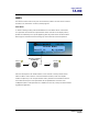
The connector wiring is as follows:
INPUT OUTPUT
PIN 1 N/C PIN 1 N/C
PIN 2 HOT (+) PIN 2 HOT (+)
PIN 3 COLD (-) PIN 3 COLD (-)
Input and Output Connector Wiring
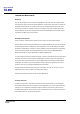
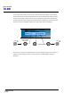
Balanced Wiring
Whether a system is wired to a 'pin 3 hot' or a 'pin 2 hot' convention will not matter as long
as the wiring of hot & cold phases to both the input and output XLR connectors is the same.
At the LMS-D6 input, the convention is 'screen goes forward with the signal'. Input cable
screening therefore needs to be connected at and derived from the signal source end, as pin
1 on the input XLR is not connected to the LMS-D6 chassis nor signal ground.
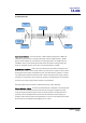
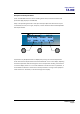
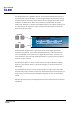
Time correction for loudspeaker driver placement
When a loudspeaker sound system is constructed which utilises different loudspeaker drivers
for separate frequency bands, it is inevitable that the sound sources are non-coincident. The
effect of this is that phase and time differences occur, producing a substantial cancellation of
the signal around the crossover region. There is also a general lack of transient clarity or
smearing of the sound, resulting from an inaccurate combining of the wavefront. The LMS-
D6 provides and maintains the optimum relative signal delay between drivers.