LMS-D4 DIGITAL LOUDSPEAKER MANAGEMENT SYSTEM USER MANUAL Turbosound Ltd. Star Road, Partridge Green West Sussex RH13 8RY England Tel: +44 (0)1403 711447 Fax: +44 (0)1403 710155 web: www.turbosound.
user manual LMS-D4 CONTENTS Important Safety Information ............................................................................................................3 Unpacking the LMS-D4 ......................................................................................................................4 Introduction ........................................................................................................................................5 Features ...........................................
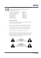
user manual LMS-D4 An example of this equipment has been tested and found to comply with the following European and international Standards for Electromagnetic Compatibility and Electrical Safety: Conducted and Absorbed Emissions (EU): EN55103 (1996) Harmonic Current Emisions (EU): EN61000-3-2 Voltage Fluctuations/Flicker (EU): EN61000-3-3 Generic Immunity (EU): EN50082-1 (1997) Electrical Safety (EU): EN60065 (1998) Electrical Safety (US): UL6500 (2000) Electrical Safety (Canada): CSA E6500 (
user manual LMS-D4 Thanks Thank you for choosing the TURBOSOUND LMS-D4 for your application. Please spare a little time to study the contents of this manual, so that you obtain the best possible performance from this unit. All TURBOSOUND products are carefully engineered for world class performance and reliability. If you would like further information about this or any other TURBOSOUND product, please contact us. We look forward to helping you in the near future.
user manual LMS-D4 Introduction The LMS-D4 is a compact and powerful DSP based audio-processing unit designed for use with particular Turbosound loudspeaker systems and associated bass enclosures, combining the functions of multiple conventional products in a compact 1U high 19” rack unit. To achieve this the LMS-D4 has 2 inputs and 4 outputs, which are configured by different system presets to allow two basic modes: stereo 2 way and mono 3 way.
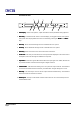
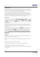
user manual LMS-D4 Front Panel Functions 3 LMS-D4 2 < BACK NEXT > MENU ENTER 6 SCROLL 8 A B 1 2 3 4 CLIP LIMIT -24 1 RS-232 MUTE DIGITAL LOUDSPEAKER MANAGEMENT SYSTEM 4 5 7 9 10 1. LCD Display - Shows menu options, output information and the parameters being adjusted. 2. Menu Key - Activates the main menu on the LCD display, and toggles between menu options and system name display. Different menus are selected by pressing the ‘BACK’ and ‘NEXT’ keys. 3.
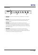
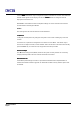
user manual LMS-D4 Rear Panel Functions 1 LMS-D4 SERIAL NO.: STAR ROAD, PARTRIDGE GREEN, WEST SUSSEX, RH13 8RY THIS APPARATUS MUST BE EARTHED. DO NOT EXPOSE THIS UNIT TO MOISTURE. DO NOT REMOVE THIS COVER. NO USER SERVICEABLE PARTS INSIDE. REPLACE FUSE WITH SAME TYPE ONLY. MADE INTHE E.U. OUTPUT 3 OUTPUT 2 OUTPUT 1 RIGHT / MONO IN LEFT IN PIN1=SHIELD PIN2=HOT PIN3=COLD POWER ~ 50/60Hz 100V-240V Fuse Sticker 2 1. OUTPUT 4 4 3 Mains Power - Connected via a standard IEC socket.
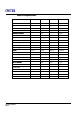
user manual LMS-D4 Outputs are configured as follows:follows:System O/P 1 O/P 2 O/P 3 O/P 4 TQTQ-308 Passive - Left - Right TQTQ-308 Pas + Sub Left Sub Left Main Right Sub Left Main TQTQ-310 Passive - Left - Right TQTQ-310 Pas + Sub Left Sub Left Main Right Sub Left Main TQTQ-310 Pas. Monitor - Left - Right TQTQ-315 Passive - Left - Right TQTQ-315 Pas + Sub Left Sub Left Main Right Sub Left Main TQTQ-315 Pas.
user manual LMS-D4 Operating the LMS-D4 With the unit mounted in a rack or cabinet, securely plug in all connections and check especially that the Low (LF or Bass) and High (HF or Top) outputs are connected to the correct amplifiers. It is good practice to switch on the LMS-D4 before powering up the amplifiers. When you plug the LMS-D4 into the mains power supply, the unit will power up and the LCD display indicates the last system loaded; the unit will be configured as it was when it was last turned off.
user manual LMS-D4 Use the ‘NEXT’ and ‘BACK’ keys to navigate through the accessible user controls. Then when the desired control appears on the display, use the the ‘SCROLL’ button to change the value as displayed on the bottom row. IMPORTANT: Check that the limiter and amplifier settings are correct and that mixer levels are minimised before unmuting the LMS-D4.
user manual LMS-D4 CROSSOVER SETTINGS 1) Input Gain INPUT GAIN Gain = 0.0dB The input gain sets the attenuation of the signal before any processing is applied. The value ranges from -40dB to +6dB in 0.5dB steps. In stereo mode the gain value applies to both inputs. 2) LF Bass Boost BASS BOOST Trim = 0.0dB Where implemented, the range of values are from +6.0 dB to –6.0 dB, in 0.5 dB steps. The corner frequency is fixed and optimised for each system, and typically it is around 100Hz.
user manual LMS-D4 3) Sub-bass channels operation mode OP1+3 Sub Mode = Stereo The possible values are ‘Stereo’ and ‘MonoSum L+R’. With a system using a stereo two way configuration and having channels 1 and 3 dedicated for sub-bass operation, it is possible to set these channels either as independent (i.e. in stereo mode) or with the signals from both Left and Right inputs summed. Note: this screen is not available on monitor programs or bi-amp with sub programs.
user manual LMS-D4 3. Scroll to set the nearest lower voltage to the calculated value in the limiter screen for that loudspeaker model (or frequency band as appropriate), and press ENTER. Refer to the limiter voltage lookup table in Appendix A for a range of approximate conversion values. In addition to those values, the limiters can also be defeated (OFF displayed on the screen).
user manual LMS-D4 Set the signal delay on the specified output channel. The delays can be adjusted in 20.83 uS increments, with a maximum value of 20.7 ms (≡ 7.1 metres) in stereo two way configurations, and 42 ms (≡ 14.4 metres) in mono three way configurations. These delays are provided (their range is large enough) to align the driver components in the time domain – including separate sub-bass cabinets – but will not replace a dedicated delay line unit in applications such as distributed systems.
user manual LMS-D4 Specifications Inputs Two electronically balanced nominally 0db Impedance 10 kOhm Outputs Four electronically balanced nominally 0db Min. Load 600 Ohm Max. Level +19dBu into 2kOhm load Frequency Resp. Resp ±0.5dB 20Hz - 20kHz Dynamic Range 110dB (typ.) 20Hz -20kHz unweighted Distortion < 0.02% @ 1kHz, +18dBu Maximum Delay up to 42 ms (increment 21 µs) Output gain adjustable -15dB to +15dB in 0.5dB steps and mute Bass Boost shelf adjustable ±6dB in 0.
user manual LMS-D4 WARRANTY This product is warranted against defects in components and workmanship only, for a period of one year from the date of shipment to the end user. During the warranty period, TURBOSOUND will, at its discretion, either repair or replace products which prove to be defective, provided that the product is returned, shipping prepaid, to an authorised TURBOSOUND service facility.
user manual LMS-D4 Turbosound Ltd Star Road, Partridge Green West Sussex RH13 8RY England Tel:+44 (0)1403 711447 Fax: +44 (0)1403 710155 web: www.turbosound.