Rigging Manual MANCHESTER SERIES MV212-XV and MV212 Dual 12" Full Size Line Array Element and Variable Curvature Line Array Element for Touring and Install Applications MV212-VT Vertical Transporter for 4 MANCHESTER MV212 Line Array Elements MS215 Dual 15" Vented Bandpass Subwoofer for Touring and Installation Applications MS215-VT Vertical Transporter for MANCHESTER MS215 Subwoofers MAN-FG Universal Fly Grid for MANCHESTER MV Line Array Elements and MS215 Subwoofers ! WARNING! This rigging manual co
MANCHESTER SERIES Rigging Manual Table of Contents Important Safety Instructions....................................... 3 Chapter 1: Safety Information....................................... 4 Chapter 2: Introduction.................................................. 6 Chapter 3: A ssembling an MV212 Array on a MAN-FG Fly Grid....................... 28 Chapter 4: A ssembling MS215 Subwoofers on a MAN-FG Fly Grid............ 32 Chapter 5: Assembling an MV212 Array with a MS215 Subwoofer..............
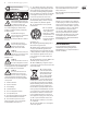
MANCHESTER SERIES Rigging Manual Important Safety Instructions Terminals marked with this symbol carry electrical current of sufficient magnitude to constitute risk of electric shock. Use only high-quality professional speaker cables with ¼" TS or twist-locking plugs pre-installed. All other installation or modification should be performed only by qualified personnel.
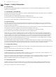
MANCHESTER SERIES Rigging Manual Chapter 1: Safety Information 1.1 Intended Use The rigging components (MAN-FG fly grid, rigging pins, mounting links) shall only be used in conjunction with Turbosound MV212 loudspeakers and MS215 subwoofers as described in this manual. 1.
MANCHESTER SERIES Rigging Manual 1.7 Secondary Safeties All loudspeakers flown in theatres, studios or other places of work and entertainment shall, in addition to the principle load bearing means of suspension, be provided with an independent, properly rated, and securely attached secondary safety. Only steel wire ropes or steel chains of an approved construction and load rating shall be used as secondary safeties. Plastic-covered steel wire ropes are not permitted for use as secondary safeties.
MANCHESTER SERIES Rigging Manual Chapter 2: Introduction 2.
MANCHESTER SERIES Rigging Manual MS215 and MV212 Mixed Array (See Chapter 5) Two MS215 Subwoofer Groundstack (See Chapter 6) Two MS218 Subwoofer Groundstack (See Chapter 6) MS215 and MV212 Array Groundstack (See Chapter 7)
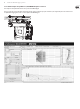
MANCHESTER SERIES Rigging Manual 2.2 Rigging and Acoustic Simulation Software The EASE FOCUS software allows you to configure the system for optimal performance and coverage in the venue. The software can be downloaded from http://www.afmg.eu/index.php/products.html The quantity of cabinets can be varied, the angles of each cabinet can be adjusted, and the SPL coverage calculated for any configuration.
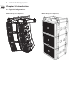
MANCHESTER SERIES Rigging Manual 2.2.2 EASE example: Array MV212 x 8, with MAN-FG Tip Bar Centered This example uses the Tip Bar mounted in the center position of the MAN FG fly grid. Note: for systems that do not require much variation in the tilt angle, and in systems that only require one main hoist, the single shackle plate can be used instead of the Tip Bar. All four rigging pins are used to secure the Tip Bar to the MAN-FG fly grid.
MANCHESTER SERIES Rigging Manual 2.2.3 EASE example: Array MV212 x 8, with MAN-FG Tip Bar Mounted Rearwards This example uses the Tip Bar mounted in the rear position on the MAN-FG fly grid. Using the Tip Bar in this position will make the array's Centre of Gravity force the array tilt downwards. All four rigging pins are used to secure the Tip Bar to the MAN-FG fly grid.
MANCHESTER SERIES Rigging Manual 2.2.4 EASE example: Array MV212 x 8, with MAN-FG Tip Bar Mounted Forwards This example uses the Tip Bar mounted in the forward position on the MAN-FG fly grid. Using the Tip Bar in this position will make the array's Centre of Gravity force the array tilt upwards. All four rigging pins are used to secure the Tip Bar to the MAN-FG fly grid.
MANCHESTER SERIES Rigging Manual 2.2.5 EASE example: Array MV212 x 24, with MAN-FG Tip Rearwards This example uses the Tip Bar mounted in the rear position on the MAN-FG fly grid. All four rigging pins are used to secure the Tip Bar to the MAN-FG fly grid.
MANCHESTER SERIES Rigging Manual 2.2.6 EASE example: Mixed Array MS215 x 6, MV212 x 16, with MAN-FG Tip Bar Mounted Rearwards This example uses the Tip Bar mounted in the rear position on the MAN-FG fly grid. All four rigging pins are used to secure the Tip Bar to the MAN-FG fly grid.
MANCHESTER SERIES Rigging Manual 2.3 MV212 Cabinet Angles The angle of each MV212 cabinet relative to the cabinet above it, is varied by inserting the quick release pin into one of the mounting holes in the rear mounting bracket. These are labeled from 0 to 10 degrees. Use the “STOW” position to securely stow the sliding mount plate in the lowest position when not in use. The Zero degrees position uses the same hole as “STOW” but is used with the sliding mount plate moved up to its highest postion.
MANCHESTER SERIES Rigging Manual Rigging Pin installation in the MV212 rear mounting plate This drawing shows the pin location used to set the angle of the cabinet relative to the cabinet above (0 degrees = Parallel). Pin location STOW (fully down) 0 degrees (fully up) 0.5 degrees 1 degrees 1.5 degrees 2 degrees 3 degrees 4 degrees 5 degrees 6 degrees 8 degrees 10 degrees 2.
MANCHESTER SERIES Rigging Manual 2.5 Weights Item MAN-FG with Tip Bar MV212 MV212-XV MS215 MS218 Quantity 1 1 1 1 1 Weight (kg) 53 53 50 83 97 Weight (lbs) 116.9 116.9 110.2 183 213.9 2.6 MAN-FG Fly Grid Working Load Limit (WLL) Item 3 Point Suspension (for MV212 and MV212-XV) 4 Point Suspension (for MS215) WLL (kg) WLL (lbs) DESIGN FACTOR 894 1971 10:1 1009 2224 10:1 2.
MANCHESTER SERIES Rigging Manual 2.8 Rigging Component Traceability Markings Each component of the rigging system is marked with a number that allows it to be identified for tracebility purposes. The illustrations below show the locations of the tracebility markings on the various components. Note: These are not part numbers for ordering spare parts.
MANCHESTER SERIES Rigging Manual 2.9 MAN-FG Fly Grid Dimensions See Chapter 9 for information regarding inspection, care, and maintenance. 181 [7.1] FRONT VIEW (WITH INTERNALS SHOWN) FRONT VIEW LEFT SIDE (WITH INTERNALS SHOWN) 825.4 [32.5] 600 [23.6] 460 [18.1] BACK 850 [33.5] FRONT LEFT SIDE VIEW TOP VIEW Dimensions in mm [Inches] 2.10 MV212 Cabinet Dimensions 490 [19.3] See Chapter 9 for information regarding inspection, care, and maintenance. TOP / BOTTOM SIDES 354 [13.9] 810 [31.
MANCHESTER SERIES Rigging Manual 2.11 MS215 Subwoofer Dimensions See Chapter 9 for information regarding inspection, care, and maintenance. SIDES 800 [31.5] 530 [20.9] BACK 810 [31.9] FRONT TOP / BOTTOM NOTE: Pole mount socket on top of box only Dimensions in mm [Inches] 2.12 MS218 Subwoofer Dimensions See Chapter 9 for information regarding inspection, care, and maintenance. SIDES BACK 800 [31.5] 560 [22] 1050 [41.
MANCHESTER SERIES Rigging Manual 2.13 Rigging Pins See Chapter 9 for information regarding inspection, care, and maintenance. These quick release pins are the fundamental mechanical fastener for the assembly of the MAN-FG fly grid, MV212 cabinet, and the MS215 subwoofer. 1. Spring Balls – These are locking devices that prevent the pin from pulling out once it has been inserted. 1 2 1 2.
MANCHESTER SERIES Rigging Manual 2.13.1 Rigging Pin Installation Pin Installation The following example shows how to use a quick release pin to join two MV212 cabinets together. This just shows one pin as an example, but all pins must be installed. Exact details of the connections for various configurations are given in the various chapters of this manual. 2 1 1. Support the weight of the components to be joined. 2. Pull out the lower pin of the top MV212 cabinet. 3.
MANCHESTER SERIES Rigging Manual 2.13.2 Typical Locations where Rigging Pins are used PINS CORRECTLY INSERTED, ALL THE WAY IN PINS CORRECTLY INSERTED, ALL THE WAY IN PINS CORRECTLY INSERTED, ALL THE WAY IN ! WARNING VERIFY THAT EACH PIN IS CORRECTLY INSERTED, AND THAT EACH PIN CANNOT BE PULLED OUT WITHOUT PRESSING THE RELEASE BUTTON FIRST. FAILURE TO FOLLOW INSTRUCTIONS MAY CAUSE PERMANENT INJURY OR DEATH.
MANCHESTER SERIES Rigging Manual 2.14 Vertical Orientation CORRECT INSTALLATION Vertical Orientation Only! The mechanical design of the MV212 cabinet, MS215 subwoofer, and the MAN-FG fly grid uses links and quick release pins to assemble the various components. The mechanical strength comes from the cabinet's metal side pieces and the pins, and not through the wooden cabinets. The cabinets are supported vertically below each other, and vertically below the fly grid.
MANCHESTER SERIES Rigging Manual 2.15 MS215 Subwoofer Mounting Components Mounting Links Out 2 1 The MS215 subwoofer has four retractable mounting links at the top (1), and four corresponding mounting holes at the bottom (3). These mounting components allow the subwoofer to be attached to the MAN-FG fly grid, or attached to other MS215 subwoofers. 4 MS215 subwoofers may also be attached to each other in rear-firing or forwardfiring orientations.
MANCHESTER SERIES Rigging Manual 2.16 MV212 Cabinet Mounting Components 2 The MV212 cabinet has two retractable mounting links (1) at the top, and an adjustable rear link (4) that allows setting of the inter-cabinet angle. There are two corresponding front slots at the bottom, and one at the rear, with securing pins. These mounting components allow the MV212 cabinets to be connected together, attached to the MAN-FG fly grid, and MS215 subwoofer with a MAN-FG fly grid. 1 4 5 3 6 1.
MANCHESTER SERIES Rigging Manual 2.17 MAN-FG Fly Grid Mounting Components 3 The MAN-FG fly grid shall only be used with MV212 cabinets and MS215 subwoofers. It is not designed to work with any other cabinets. Tip Bar 6 4 7 Front 5 1 11 2 10 7 8 Front 9 Single Point Shackle Plate 5 Front MV212 ground stack angle plate 4 Front 1. Mounting Links – These retractable links connect the fly grid to the bottom mounting slots of an MV212 cabinet or MS215 subwoofer.
MANCHESTER SERIES Rigging Manual Recommended Bow Shackles Suspend the array by attaching one or more bow shackles or similar lifting devices with a pin diameter to fit the 20 mm suspension pick points on the Tip Bar or the single shackle plate of the MAN-FG fly grid. 43 mm WARNING: THE BOW SHACKLE MUST BE RATED AT 3.25 TONNES. 74 mm Installation and setup should only be carried out by qualified and authorized personnel observing the valid national Rules for the Prevention of Accidents (RPA).
MANCHESTER SERIES Rigging Manual Chapter 3: Assembling an MV212 Array on a MAN-FG Fly Grid The following procedure shows how to build an array of MV212 cabinets by adding them one at a time. Alternatively, cabinets can be pre-assembled into groups of four, and then connected to the fly grid at a later time. This method is shown in procedure 3.2. The system is suspended using a MAN-FG fly grid that attaches to your lifting system.
MANCHESTER SERIES Rigging Manual Procedure 3.1 Connecting MV212 Cabinets to the MAN-FG 1. Install the Tip Bar (1) onto the MAN-FG fly grid and secure using the 4 rigging pins (2). 2. Double check that all pins are correctly inserted, before proceeding further. 1 2 3 6 4. Prepare all the MV212 cabinets, by pulling out the front rigging pins (6), so the spring-loaded top links (5) will move to the up position. Reinsert the pins (6) to secure the links in the up position.
MANCHESTER SERIES Rigging Manual 12. The addition of other MV212 cabinets is performed by repeating steps 8 through 11 for each additional cabinet. ! WARNING DO NOT EXCEED A TOTAL QUANTITY OF 16 MV212 CABINETS FOR ONE MAN-FG FLY GRID. FAILURE TO FOLLOW INSTRUCTIONS MAY CAUSE PERMANENT INJURY OR DEATH. NOTE Disassembly is the reverse of assembly.
MANCHESTER SERIES Rigging Manual Procedure 3.2: Adding a group of MV212 Cabinets to the MAN-FG Fly Grid Groups of MV212 cabinets can be pre-assembled using Procedure 3.1, steps 8 to 11, and then connected to the MAN-FG fly grid as an assembled group just prior to flying. The MV212 cabinets connect to each other using the front mounting links (3), and the rear mounting plate (5). 1 4 3 2 5 6 1.
MANCHESTER SERIES Rigging Manual Chapter 4: Assembling MS215 Subwoofers on a MAN-FG Fly Grid The following procedure describes how to assemble a MS215 subwoofer to the MAN-FG fly grid. The MAN-FG fly grid is attached to the top of the MS215 subwoofer, using the subwoofer's 4 mounting links, and four lower rigging pins of the MAN-FG fly grid. ! WARNING DO NOT EXCEED A TOTAL QUANTITY OF 12 MS215 SUBWOOFERS FOR ONE MAN-FG FLY GRID. FAILURE TO FOLLOW INSTRUCTIONS MAY CAUSE PERMANENT INJURY OR DEATH. 4.
MANCHESTER SERIES Rigging Manual Procedure 4.1 Connecting MS215 Subwoofers to the MAN-FG Fly Grid 2 1 5 4 1. Prepare the MAN-FG fly grid by pulling out the 4 lower rigging pins (1). Attach the single shackle plate (2) using its 2 rigging pins (3), to the fly grid mounting position recommended by the EASE FOCUS software. 2. Prepare the MS215 subwoofer by pulling out its 4 top pins (4) so the top links (5) spring up. Reinsert the top pins (4) to secure the links in the up position.
MANCHESTER SERIES Rigging Manual 6. Prepare the upper subwoofer by removing its 4 lower pins (6). 7. Prepare the lower subwoofer by pulling out its 4 top pins (4) so the top links (5) spring up. Reinsert the top pins (4) to secure the links in the up position. 8. Carefully lower the upper subwoofer and fly grid assembly onto the lower subwoofer, and align the lower subwoofer's top links (5) with the corresponding slots in the bottom of the upper subwoofer.
MANCHESTER SERIES Rigging Manual Chapter 5: Assembling an MV212 Array with a MS215 Subwoofer The following procedure describes how to assemble a mixed array consisting of one MS215 subwoofer and MV212 cabinets below it. One MAN-FG fly grid is attached to the top of the MS215 subwoofer, using components supplied with the MAN-FG fly grid. A second MAN-FG fly grid is attached to the bottom of the lowest MS215 subwoofer, using components supplied with the MAN-FG fly grid.
MANCHESTER SERIES Rigging Manual Procedure 5.1 - Attaching the MAN-FG fly grids to the MS215 Subwoofer 1. Perform the previous procedure in Chapter 4: Procedure 4.1 steps 1 to 3, to attach the MAN-FG fly grid to the MS215 subwoofer. Procedure Description of Work 4.1 step 1 to step 3 Attaching the MS215 Subwoofer to the MAN-FG Fly Grid Check Double check all pins are correctly inserted, and that the fly grid is securely attached to the subwoofer. 1 2.
MANCHESTER SERIES Rigging Manual Procedure 5.2 - Attaching the MV212 Cabinets to the MS215 Subwoofer 1. Perform the previous procedure in Chapter 3: Procedure 3.1 steps 3 to 12, to attach MV212 cabinets to the lower MAN-FG fly grid. Procedure Description of Work 3.1 step 3 to step 12 Connecting MV212 cabinets to the MAN-FG fly grid Check Double check all pins are correctly inserted, and that the MV212 cabinets are securely attached to the MAN-FG fly grid. 2.
MANCHESTER SERIES Rigging Manual ! WARNING VARIOUS MIXTURES OF MV212 CABINETS AND MS215 SUBWOOFERS CAN BE CONFIGURED BUT DO NOT EXCEED A TOTAL WEIGHT OF 1009 KG. ! WARNING THIS ARRAY SHALL ONLY BE MADE WITH THE MS215 SUBWOOFER ON TOP, AND THE MV212 CABINETS BELOW. FAILURE TO FOLLOW INSTRUCTIONS MAY CAUSE PERMANENT INJURY OR DEATH.
MANCHESTER SERIES Rigging Manual Chapter 6: Groundstack of two MS215 Subwoofers The following procedure describes how to assemble a groundstack with two MS215 subwoofers. The MS215 subwoofers are attached using the 4 pop up mounting links of the lower subwoofer. ! WARNING DO NOT EXCEED A TOTAL QUANTITY OF 3 MS215 SUBWOOFERS FOR THIS GROUNDSTACK CONFIGURATION. FAILURE TO FOLLOW INSTRUCTIONS MAY CAUSE PERMANENT INJURY OR DEATH.
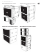
MANCHESTER SERIES Rigging Manual Procedure 6.1 - Assembling two MS215 Subwoofers 1. Prior to stacking, ensure that the lower subwoofer is mounted on a flat, dry, and solid horizontal surface, capable of safely bearing the weight of the assembly. 2. Pull out the lower subwoofer's 4 upper pins (2), and the spring-loaded mounting links (3) will move to the up position. Reinsert the pins (2) to secure the links (3) in the up position. 3. Pull out the upper subwoofer's 4 lower pins (1).
MANCHESTER SERIES Rigging Manual Procedure 6.2 - Assembling two MS218 Subwoofers The following procedure describes how to assemble a groundstack with two MS218 subwoofers. 1. Prior to stacking, ensure that the lower subwoofer is mounted on a flat, dry, and solid horizontal surface, capable of safely bearing the weight of the assembly. 2. With the help of assistants, carefully lift the second MS218 subwoofer on top of the lower subwoofer.
MANCHESTER SERIES Rigging Manual Chapter 7: Groundstack MS215 Subwoofer and MV212 Array The following procedure describes how to assemble a groundstack with a MS215 subwoofer as a base, and an array of four MV212 cabinets on top. ! WARNING DO NOT EXCEED A TOTAL QUANTITY OF 6 x MV212 CABINETS FOR THIS GROUNDSTACK CONFIGURATION. FAILURE TO FOLLOW INSTRUCTIONS MAY CAUSE PERMANENT INJURY OR DEATH.
MANCHESTER SERIES Rigging Manual Procedure 7.1 - Attaching the MAN-FG fly grid to the MS215 Subwoofer stack 2 1 2 1. Perform the previous procedures in Chapter 4 to attach the MAN-FG fly grid to the MS215 subwoofer(s). 3 1 Procedure 4.1 Description of Work Check Attaching the MS215 Subwoofer to the MAN-FG fly grid Double check all pins are correctly inserted, and that the MAN-FG fly grid is securely attached. 2.
MANCHESTER SERIES Rigging Manual 5. Prepare the first MV212 cabinet, by pulling out the front lower rigging pins (6), and the rear lower rigging pin (7). 6. Carefully lift the MV212 cabinet until its lower front mounting slots fit over the 2 front links (1) of the MAN-FG fly grid. Reinsert the front pins (6) to secure the MAN-FG fly grid links (1) to the MV212. 7 6 1 8 1 Take care not to trap your fingers between components. 4 7.
MANCHESTER SERIES Rigging Manual Procedure 7.1 - continued 10. Prepare the next MV212 cabinet, by pulling out the front lower rigging pins (6), and the rear lower rigging pin (7). (See step 5.) 11. Carefully lift the MV212 cabinet until its lower front mounting slots fit over the links (10) of the lower MV212. Reinsert the front pins (6) to secure the links (10) to the lower MV212. 10 9 6 7 10 Take care not to trap your fingers between components. 11 12 12.
MANCHESTER SERIES Rigging Manual Chapter 8: MV212-VT and MS215-VT Vertical Transporters 8.0.3 Measured Weights Item Quantity Weight MS215 -VT 1 31.6 kg 69.7 lbs MV212-VT 1 24.7 kg 54.5 lbs The MS215-VT allows a stack of up to 3 MS215 subwoofers to be transported and stored securely, and moved into postion for flying. The MV212-VT allows a stack of up to 4 MV212 cabinets to be transported and stored securely, and moved into postion for flying.
MANCHESTER SERIES Rigging Manual 8. 1 Attaching MV212 cabinets to the MV212-VT 1. Prepare the first MV212 cabinet, by pulling out the front lower rigging pins (1), and the rear lower rigging pin (2). 2. Carefully lift the MV212 cabinet until its lower front mounting slots fit over the 2 front mounting links (3) of the MV212-VT. Reinsert the front pins (1) to secure the MV212-VT mounting links (3) to the MV212. Take care not to trap your fingers between components. 2 1 3 4 3 3.
MANCHESTER SERIES Rigging Manual 8. 2 Attaching MS215 subwoofers to the MS215-VT 1. Prepare the first MS215 subwoofer, by pulling out the 4 lower rigging pins (1). 5 2. Carefully lift the MS215 subwoofer until its mounting slots fit over the 4 mounting links (2) of the MS215-VT. Reinsert the pins (1) to secure the subwoofer cabinet to the mounting links (2). 5 Take care not to trap your fingers between components.
MANCHESTER SERIES Rigging Manual Chapter 9: Safety Inspection ! The following notes must be read and followed before suspending the systems or ground stacking: Cabinets Inspect all cabinets carefully and make sure that all surfaces are clean, in good condition, and free from cracks, corrosion, or any other defects that may weaken the assembly. Check for any missing screws, rigging pins, pop up links, mounting links, or pivot pins.
MANCHESTER SERIES Rigging Manual Chapter 10: Enclosure quantities and combinations for MAN-FG fly grid suspension at 10:1, 7:1, and 5:1 design factors Maximum allowed MV212 and MS215 enclosure quantities and combinations for suspension using MAN-FG Fly Bar at 10:1, 7:1 and 5:1 design factors. MAN-FG Working Load Limit W.L.L Suspension W.L.
MANCHESTER SERIES Rigging Manual MS215 Arrays Safety Factor Qty MS215 Weights kg 10 to 1 10 to 1 10 to 1 10 to 1 10 to 1 10 to 1 10 to 1 10 to 1 10 to 1 10 to 1 10 to 1 10 to 1 7 to 1 7 to 1 7 to 1 7 to 1 7 to 1 7 to 1 1 2 3 4 5 6 7 8 9 10 11 12 13 14 15 16 17 18 83 166 249 332 415 498 581 664 747 830 913 996 1079 1162 1245 1328 1411 1494 Description Maximum quantity at 10:1 Maximum quantity at 7:1 Mixed Array Examples Example A: 8 x MV212 and 6 x MS215 Safety Factor = 10:1 Qty of MV212 MV212
MANCHESTER SERIES Rigging Manual Example B: 12 x MV212 and 3 x MS215 Safety Factor = 10:1 Qty of MV212 MV212 Weights kg Qty of MS215 MS215 Weights kg 1 2 3 4 5 6 7 8 9 10 11 12 106 159 212 265 318 371 424 477 530 583 636 689 1 2 3 83 166 249 TOTAL 938 kg Note: 2nd MAN-FG Fly Grid must be included in total weight load on 1st MAN-FG Example C: 12 x MV212 and 6 x MS215 Safety Factor = 7:1 Qty of MV212 MV212 Weights kg Qty of MS215 MS215 Weights kg 1 2 3 4 5 6 7 8 9 10 11 12 106 159 212 265 3
MANCHESTER SERIES Rigging Manual Manufacturer’s Declaration We, Music Tribe Global Brands Ltd. Music Tribe Global Brands Ltd. 26th Floor, Centuria Medical Makati Century City Makati City, Manila 1200, PH Do hereby declare that the following components: MV212 (and variants) Loudspeaker Cabinets MS215 Subwoofer Cabinets MAN-FG Fly Grid Tip Bar, Single Point Shackle Plate, Ground Stack Plate are in compliance with the relevant fundamental safety and health criteria of the applicable EC Directive(s).