
Manual

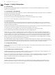
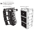
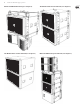

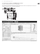

Table Of Contents
- Important Safety Instructions
- Chapter 1: Safety Information
- Chapter 2: Introduction
- Chapter 3: Assembling an MV212 Array on a MAN-FG Fly Grid
- Chapter 4: Assembling MS215 Subwoofers on a MAN-FG Fly Grid
- Chapter 5: Assembling an MV212 Array with a MS215 Subwoofer
- Chapter 6: Groundstack of two MS215 Subwoofers
- Chapter 7: Groundstack MS215 Subwoofer and MV212 Array
- Chapter 8: MV212-VT and MS215-VT Vertical Transporters
- Chapter 9: Safety Inspection
- Chapter 10: Enclosure quantities and combinations for MAN-FG fly grid suspension at 10:1, 7:1, and 5:1 design factors

9 MANCHESTER SERIES Rigging Manual
2.2.2 EASE example: Array MV212 x 8, with MAN-FG Tip Bar Centered
This example uses the Tip Bar mounted in the center position of the MAN FG y grid.
Note: for systems that do not require much variation in the tilt angle, and in systems that only require one main hoist, the single shackle plate can be used instead of
the Tip Bar. All four rigging pins are used to secure the Tip Bar to the MAN-FG y grid.