TBV BERLIN SERIES TBV118L 18" Front Loaded Subwoofer for Touring, Portable and Installation Applications TBV123 Arrayable 2 Way 12" Constant Curvature Loudspeaker with Dendritic Waveguide for Touring, Portable and Installation Applications TBV118L-AN 18" Powered Subwoofer with KLARK TEKNIK DSP Technology and ULTRANET Networking TBV123-AN Arrayable 2 Way 12" Constant Curvature Loudspeaker with Dendritic Waveguide, KLARK TEKNIK DSP Technology and ULTRANET Networking TBV123-FB Fly Bar for TBV BERLIN Series
TBV123 / TBV123-AN and TBV118L / TBV118L-AN Rigging Manual Table of Contents Important Safety Instructions...............................................................................................................3 Legal Disclaimer......................................................................................................................................3 Limited warranty.........................................................................................................................
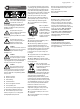
Rigging Manual Important Safety Instructions Terminals marked with this symbol carry electrical current of sufficient magnitude to constitute risk of electric shock. Use only high-quality professional speaker cables with ¼" TS or twist-locking plugs pre-installed. All other installation or modification should be performed only by qualified personnel.
TBV123 / TBV123-AN and TBV118L / TBV118L-AN Rigging Manual Chapter 1: Safety Information 1.1 Intended Use The rigging components (TBV123-FB flybar, rigging pins, mounting links) shall only be used in conjunction with TURBOSOUND TBV123, TBV123-AN loudspeakers and TBV118L and TBV118L-AN subwoofers as described in this manual. NOTE: Throughout this manual, and unless otherwise noted, the term "TBV123" refers to the TBV123 passive loudspeaker or the TBV123-AN powered loudspeaker.
Rigging Manual 1.6 5 Safety Inspections Carefully inspect rigging system components and cabinets for defects or signs of damage before proceeding to assemble the array to be flown. If any parts are damaged or suspect, or if there is any doubt as to the proper functioning and safety of the items DO NOT USE THEM and withdraw them from use immediately. Refer to Chapter 12 for information about care maintenance and disposal. 1.
TBV123 / TBV123-AN and TBV118L / TBV118L-AN Rigging Manual Chapter 2: Introduction 2.
Rigging Manual 7 TBV118L Subwoofer Ground Stack (See Chapter 6) TBV118L and TBV123 Array Ground Stack (See Chapter 7) TBV123 Array Ground Stack (See Chapter 8) TBV118L and TBV123 Array Pole Mount (See Chapter 9)
TBV123 / TBV123-AN and TBV118L / TBV118L-AN Rigging Manual 2.2 Rigging and Acoustic Simulation Software The EASE FOCUS II software allows you to configure the system for optimal performance and coverage in the venue. The software can be downloaded from http://www.afmg.eu/index.php/products.html Further information about the TBV models is available from www.turbosound.com The TBV123 is a constant curvature line array, and the inter-cabinet angle is fixed at 15 degrees.
Rigging Manual 2.3 Weights Item TBV123 Quantity 1 2 3 4 5 6 Weight (kg) 22.0 44.0 66.0 88.0 110.0 132.0 Weight (lbs) 48.5 97.0 145.5 194.0 242.5 291.0 Item TBV118L Quantity 1 2 3 4 5 Weight (kg) 37.0 74.0 111.0 148.0 185.0 Weight (lbs) 81.6 163.1 244.7 326.3 407.9 Item TBV123-AN Quantity 1 2 3 4 5 6 Weight (kg) 23.0 46.0 69.0 92.0 115.0 138.0 Weight (lbs) 50.7 101.4 152.1 202.8 253.5 304.2 Item TBV118L-AN Quantity 1 2 3 4 5 Weight (kg) 38.5 77.0 115.5 154.0 192.5 Weight (lbs) 84.9 169.8 254.
TBV123 / TBV123-AN and TBV118L / TBV118L-AN Rigging Manual 2.6 TBV123-FB Flybar Dimensions See Chapter 12 for information regarding inspection, care, and maintenance. 590.00 [23.2] 525.00 [20.7] 460.00 [18.1] 395.00 [15.6] 330.00 [13.0] 170.00 [6.7] 635.00 [25.0] 47.84 [1.9] 292.00 [11.5] 153.00 [6.0] Ø13 [0.5"] 10.00 [0.4] 614.00 [24.2] 25.00 [1.0] 544.00 [21.4] 583.00 [23.0] 38.00 [1.5] 57.00 [2.2] 2.
Rigging Manual 2.8 TBV118L Subwoofer Dimensions See Chapter 12 for information regarding inspection, care, and maintenance. 485 [19.1"] Eyebolt 172 [6.8"] 255 [10.0"] 598 [23.5"] 513 [20.2"] 751 [29.6"] 485 [19.1"] Eyebolt 172 [6.
TBV123 / TBV123-AN and TBV118L / TBV118L-AN Rigging Manual 2.9 Rigging Pins See Chapter 12 for information regarding inspection, care, and maintenance. These pins are the fundamental mechanical fastener for the assembly of the TBV123-FB flybar, TBV123 cabinet, and the TBV118L subwoofer. The rigging pins for the cabinets and subwoofer have an "L" shape. The pins used for assembling the TBV123-FB flybar are straight, and should only be used for the flybar connections. 1.
Rigging Manual 13 2.9.1 Rigging Pin Installation Pin Installation The following example shows how to use the rigging pins to join two TBV123 cabinets together. Exact details are given in later chapters of this manual. 1. Support the weight of the cabinets to be joined. 1 2. Align the top mounting link (1) of the lower TBV123 cabinet with the corresponding mounting holes in the upper TBV123 cabinet. Align the link with the mounting holes so the pin can pass through and join them together. 3 2 3 3.
TBV123 / TBV123-AN and TBV118L / TBV118L-AN Rigging Manual 2.9.2 Typical Locations where Rigging Pins are used Pins correctly inserted, all the way in Pins correctly inserted, all the way in, and arm clipped in place !!WARNING VERIFY THAT EACH PIN IS CORRECTLY INSERTED, AND THAT EACH PIN CANNOT BE PULLED OUT WITHOUT PRESSING THE RELEASE BUTTON FIRST. FAILURE TO FOLLOW INSTRUCTIONS MAY CAUSE PERMANENT INJURY OR DEATH.
Rigging Manual 15 2.10 Vertical Orientation Vertical Orientation Only! The mechanical design of the TBV123 cabinet, TBV118L subwoofer, and the TBV123-FB flybar uses mounting links and rigging pins to assemble the various components. The mechanical strength comes from the cabinet's metal side pieces and the pins, and not through the wooden cabinets. The cabinets are supported vertically below each other, and vertically below the flybar.
TBV123 / TBV123-AN and TBV118L / TBV118L-AN Rigging Manual 2.11 TBV118L Subwoofer Mounting Components Mounting Links Down 1 2 3 The TBV118L subwoofer has two retractable mounting links at the top (4), that allow it to be attached to a TBV123-FB flybar, or to another TBV118L subwoofer, or to a TBV123 cabinet. Eyebolt holes and a pole mount hole are also present. 1.
Rigging Manual 2.12 TBV123 Cabinet Mounting Components Mounting Links Down The TBV123 cabinet has two retractable mounting links at the top (3), that allow it to be attached to a TBV123-FB flybar, to another TBV123 cabinet, or to a TBV118L subwoofer. Eyebolt holes and pole mount holes are also present. 1 2 3 4 1. Eyebolt locations – 4 threaded holes (2 top, 2 bottom) allow eyebolts to be fitted for flying the TBV123 cabinet without the TBV123-FB flybar. 2.
TBV123 / TBV123-AN and TBV118L / TBV118L-AN Rigging Manual 2.13 TBV123-FB Flybar Mounting Components Flybar Unassembled 4 5 3 3 1 2 Flybar Assembled 5 The TBV123-FB flybar shall only be used with TBV123 cabinets and TBV118L subwoofers. Before use, it must be assembled by securing the arms to the main bar using the supplied rigging pins. 1. Main Bar – The main bar has six suspension pick points including one at the front.
Rigging Manual 19 Chapter 3: Assembling a TBV123 Array on a TBV123-FB Flybar The following procedure shows how to build an array of TBV123 cabinets by adding them one at a time, up to a maximum of 4. Alternatively, the cabinets can be pre-assembled into a group of 4, and then connected to the flybar at a later time. The system is flown using a TBV123-FB flybar that attaches to your lifting system. The top TBV123 cabinet connects to two mounting points on the flybar.
TBV123 / TBV123-AN and TBV118L / TBV118L-AN Rigging Manual Procedure 3.1 Attaching a TBV123 Cabinet to the TBV123-FB Flybar 1. Assemble the flybar as shown on page 18. 2. Remove the rigging pins (2) from the TBV123 cabinet and lift up the 2 mounting links (1). Place the rigging pins back into their storage positions. 3. Lift the assembled TBV123-FB flybar into position above the prepared TBV123 cabinet. 1 1 Take care not to trap your fingers between components. 2 4.
Rigging Manual 21 Procedure 3.2 Attaching further TBV123 Cabinets 1. Prepare the next TBV123 cabinet, by lifting the mounting links (1) to the upwards position. The rigging pins (2) will be used to secure this cabinet to the TBV123 cabinet above. 2. Attach the bow shackle or other lifting equipment securely to the flybar mounting hole recommended by the EASE FOCUS II software, then attach the hook and chain. 2 3.
TBV123 / TBV123-AN and TBV118L / TBV118L-AN Rigging Manual Chapter 4: Assembling a TBV118L Array on a TBV123-FB Flybar The following procedure shows how to build an array of TBV118L subwoofers by adding them one at a time, up to a maximum of 2. The system is flown using a TBV123-FB flybar that attaches to your lifting system. The top TBV118L subwoofer connects to two mounting points on the flybar.
Rigging Manual 23 Procedure 4.1 Assembling a TBV118L Array on a TBV123-FB Flybar 1. Prepare the TBV118L subwoofer, by removing the rigging pins (2) and lifting the mounting links (1) to the upwards position. 3 3 1 2 2. Lift the assembled TBV123-FB flybar into position above the prepared TBV118L subwoofer. Take care not to trap your fingers between components. 3.
TBV123 / TBV123-AN and TBV118L / TBV118L-AN Rigging Manual Procedure 4.1 continued 5. If you are flying just one TBV118L subwoofer, then this completes the assembly procedure. To add another TBV118L subwoofer, continue with the procedure steps below. 6. Attach the bow shackle or other lifting equipment securely to the flybar mounting hole recommended by the EASE FOCUS II software, then attach the hook and chain. 7.
Rigging Manual 25 Chapter 5: Assembling a Mixed Array on a TBV123-FB Flybar The following procedure shows how to build a mixed array of one TBV118L subwoofer and 2 TBV123 cabinets. The system is flown using a TBV123-FB flybar that attaches to your lifting system. The TBV118L subwoofer connects to the mounting points on the flybar. The top TBV123 cabinet connects to the subwoofer above using the integral mounting points and rigging pins. No tools are required.
TBV123 / TBV123-AN and TBV118L / TBV118L-AN Rigging Manual Procedure 5.1 Assembling a Mixed Array on a TBV123-FB Flybar 1. Assemble the TBV123-FB flybar and a TBV118L subwoofer as shown in procedure 4.1. 2. Attach the bow shackle or other lifting equipment securely to the flybar mounting hole recommended by the EASE FOCUS II software, then attach the hook and chain. 1 3.
Rigging Manual 2 27 7. Adjust the position of the mounting links (1) of the TBV123 cabinet to align with the lower mounting holes of the upper TBV123 cabinet. Fully insert the rigging pins (2) and rotate the arms until they are held in place by the clips. This will further secure the rigging pins and also prevent them from rattling from audio vibrations during operation. Double check that all pins are correctly inserted, before proceeding further. 1 8.
TBV123 / TBV123-AN and TBV118L / TBV118L-AN Rigging Manual Chapter 6: Assembling a TBV118L Ground Stack The following procedure shows how to build a ground stack of TBV118L subwoofers by adding them one at a time, up to a maximum of 3. Each TBV118L subwoofer connects to the subwoofer above using the integral mounting points and rigging pins. No tools are required. !!WARNING DO NOT EXCEED A TOTAL QUANTITY OF 3 TBV118L SUBWOOFERS FOR THIS GROUND STACK CONFIGURATION.
Rigging Manual 29 Procedure 6.1 Assembling a TBV118L Ground Stack 1. Prepare the first TBV118L subwoofer, by lifting the mounting links (1) to the upwards position. The rigging pins (2) will be used to secure this subwoofer to the subwoofer to be added on top. 1 1 2 2. Carefully position the next TBV118L subwoofer until it is on top of the prepared lower subwoofer. The feet of the top subwoofer should fit into the recesses on the top surface of the lower subwoofer.
TBV123 / TBV123-AN and TBV118L / TBV118L-AN Rigging Manual Procedure 6.1 continued 4. The addition of other TBV118L subwoofers is performed by repeating steps 1, 2 and 3 for each additional subwoofer. 5. Make sure that the assembly is securely tied down with guy wires to prevent tipping. !!WARNING DO NOT EXCEED A TOTAL QUANTITY OF 3 TBV118L SUBWOOFERS FOR THIS GROUND STACK CONFIGURATION. FAILURE TO FOLLOW INSTRUCTIONS MAY CAUSE PERMANENT INJURY OR DEATH.
Rigging Manual 31 Chapter 7: Assembling a TBV118L Subwoofer and TBV123 Ground Stack The following procedure describes how to assemble a ground stack with a TBV118L subwoofer as a base and and one or two TBV123 cabinets on top. The TBV123 cabinet connects to the TBV118L subwoofer using the integral mounting points and rigging pins. No tools are required. !!WARNING DO NOT EXCEED A TOTAL QUANTITY OF 2 TBV118L SUBWOOFER AND 3 TBV123 CABINETS FOR THIS GROUND STACK CONFIGURATION.
TBV123 / TBV123-AN and TBV118L / TBV118L-AN Rigging Manual Procedure 7.1 - Assembling a TBV118L Subwoofer and TBV123 Ground Stack 1. Prepare the TBV118L subwoofer, by lifting the mounting links (1) to the upwards position. The rigging pins (2) will be used to secure this subwoofer to the TBV123 cabinet on top. 1 1 2 2. Carefully position the TBV123 cabinet until it is on top of the prepared lower subwoofer.
Rigging Manual 33 4. A second TBV123 cabinet can be added to the ground stack. Lower it onto the first TBV123 cabinet and make sure its feet fit into the recesses on the top surface of the first TBV123 cabinet. Attach it to the mounting links of the first TBV123 cabinet, and secure with the rigging pins in the same way as shown in step 3. Take care not to trap your fingers between components. Double check that all pins are correctly inserted.
TBV123 / TBV123-AN and TBV118L / TBV118L-AN Rigging Manual Chapter 8: Assembling a TBV123 Array Ground Stack The following procedure describes how to assemble a ground stack with TBV123 cabinets mounted on a TBV123-FB flybar as a base. The TBV123 cabinets connect to each other and the TBV123-FB flybar using the integral mounting points and rigging pins. No tools are required. The purpose of the TBV123-FB flybar is to add stability and prevent the ground stack from tipping backwards.
Rigging Manual 35 Procedure 8.1 - Assembling a TBV123 Array Ground Stack 1. Prepare the TBV123-FB flybar by adding the extra mounting links (supplied with the flybar) to the end of each arm. Lift the mounting links to the upwards position. Double check that all pins are correctly inserted, before proceeding further. 2. Carefully position the TBV123 cabinet until it is on top of the prepared TBV123-FB flybar.
TBV123 / TBV123-AN and TBV118L / TBV118L-AN Rigging Manual Procedure 8.1 continued 4. Lower the second TBV123 cabinet onto the first TBV123 cabinet and make sure its feet fit into the recesses on the top surface of the first TBV123 cabinet. Attach it to the mounting links of the first TBV123 cabinet, and secure with the rigging pins in the same way as shown in step 3. Take care not to trap your fingers between components.
Rigging Manual 37 Chapter 9: Pole Mounting a TBV123 Cabinet on a TBV118L Subwoofer The following procedure describes how to pole mount a TBV123 cabinet onto a TBV118L Subwoofer. The subwoofer has a top panel M20 thread mount receptacle that can accept an optional distance rod accessory and the TBV123 has two pole mount receptacles underneath that allow it to be mounted at two different angles for best coverage. The M20 distance rods are available in three different lengths: 60, 90, and 120 cm.
TBV123 / TBV123-AN and TBV118L / TBV118L-AN Rigging Manual Procedure 9.1 - Pole mounting a TBV123 cabinet on a TBV118L subwoofer 1. S crew the pole into the top of the TBV118L subwoofer using the M20 threaded attachment, and make sure it is tight and secure. 2. Carefully position the TBV123 cabinet until one of its mounting holes fits over the top of the pole, then lower it fully down onto the pole. 3. There are two holes to choose from; the front hole allows the TBV123 cabinet to tilt down.
Rigging Manual 39 Chapter 10: Assembling an Inverted TBV123 Array The TBV123 cabinets may be mounted inverted on the TBV123-FB flybar to create a mirror-image to complement TBV123 cabinets in their normal orientation.
TBV123 / TBV123-AN and TBV118L / TBV118L-AN Rigging Manual Procedure 10.1 - Assembling an Inverted TBV123 Array 1. Prepare the TBV123-FB flybar by adding the extra mounting links (supplied with the flybar) to the end of each arm. Double check that all pins are correctly inserted, before proceeding further. 2. Invert the first TBV123 cabinet and remove its rigging pins so the mounting links drop down. Carefully position the TBV123-FB flybar until it is on top of the inverted TBV123 cabinet.
Rigging Manual 41 4. Attach the bow shackle or other lifting equipment securely to the flybar mounting hole recommended by the EASE FOCUS II software, then attach the hook and chain. 5. Prepare the next TBV123 cabinet, by removing the rigging pins (2) so the mounting links drop down. 6. Carefully hoist and position the flybar and cabinet assembly until it is on top of the lower cabinet. The feet of the lower cabinet should fit into the recesses on the bottom of the top cabinet.
TBV123 / TBV123-AN and TBV118L / TBV118L-AN Rigging Manual 10.2 Assembling an Inverted Mixed Array An inverted mixed array can be assembled by attaching an inverted TBV118L cabinet to the TBV123-FB flybar, using the extra mounting links (1) supplied with the flybar. Inverted TBV123 cabinets can then be attached to the lower side of the inverted TBV118L cabinet. 3 1.
Rigging Manual 43 4. Attach the bow shackle or other lifting equipment securely to the flybar mounting hole recommended by the EASE FOCUS II software, then attach the hook and chain. 5. Prepare the inverted TBV123 cabinet. Carefully hoist and position the flybar and cabinet assembly until it is on top of the TBV123 cabinet. The feet of the TBV123 cabinet should fit into the recesses on the bottom of the TBV118L cabinet. 4 Take care not to trap your fingers between components. 3 5 6 6.
TBV123 / TBV123-AN and TBV118L / TBV118L-AN Rigging Manual 7. If you are only adding one inverted TBV123 cabinet, then this completes the procedure. 8. Carefully hoist and position the flybar/subwoofer/cabinet assembly until it is on top of the prepared lower TBV123 cabinet. The feet of the upper TBV123 cabinet should fit into the recesses on top of the lower cabinet. Take care not to trap your fingers between components. 5 6 9.
Rigging Manual 45 Chapter 11: Using Eyebolts The various arrays shown in this manual may be flown using 2 eyebolts instead of the TBV123-FB flybar. The recommended eyebolt is M10, with a thread greater than 18 mm, and a working load limit adequate for the size of the specific array to be suspended. Third party eyebolts must be specified and supplied by authorised, qualified personnel.
TBV123 / TBV123-AN and TBV118L / TBV118L-AN Rigging Manual The TBV123 cabinets and TBV118L cabinets may be flown individually, or assembled into the arrays shown in this manual. Threaded Eyebolt Holes 1. If flying individually, the top 2 eyebolts are used for suspension, and the lower 2 eyebolts can be used for positioning or flying inverted. 2.
Rigging Manual 47 Chapter 12: Safety Inspection !!The following notes must be read and followed before suspending the systems or ground stacking: Cabinets Inspect all cabinets carefully and make sure that all surfaces are clean, in good condition, and free from cracks, corrosion, or any other defects that may weaken the assembly. Check for any missing screws, rigging pins, mounting links, pivot pins, or their nuts.
TBV123 / TBV123-AN and TBV118L / TBV118L-AN Rigging Manual Chapter 13: TBV Enclosure Quantities and Combinations for TBV123-FB Flybar Suspension at 10:1, 7:1, 5:1 Design Factors Maximum allowed TBV enclosure quantities and combinations for suspension using TBV123-FB Fly Bar at 10:1, 7:1 and 5:1 design factors. 10:1 DESIGN FACTOR TBV123-FB FLY BAR SUSPENSION - ACTIVE OR PASSIVE TBV118L-AN 2 1 0 TBV123-AN 0 2 4 System 82.2 kg 89.7 kg 97.2 kg Weight 181.2 lbs 197.8 lbs 214.
Rigging Manual Manufacturer’s Declaration We, MUSIC Group Manufacturing PH Ltd. MUSIC Group Manufacturing PH Ltd. 17A Brunswick Street Hamilton HM 10 Bermuda Do hereby declare that the following components: TBV123 and TBV123-AN Loudspeaker Cabinets TBV118L and TBV118L-AN Subwoofer Cabinets TBV123-FB Flybar are in compliance with the relevant fundamental safety and health criteria of the applicable EC Directive(s). This declaration is void if unauthorised modifications are made to the equipment.