
User's Manual
pressed. Valid keys are ‘0’ through ‘9’.
Valid RF Channels are ‘1’ through ‘82’.
While in Set RF Channel mode pressing a
valid key will cause the status LED to
briefly flash YELLOW. When Set RF
Channel Mode exits, the status LED
indicates the result as follows:
SOLID GREEN - Set
RF Channel successful
SOLID RED - Set
RF Channel failed
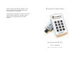
Overview:
The RI RF LCD Keypad is designed to be used with
the RI RF Receiver connected to a PC. The keypad
transmits key presses via radio frequency to the RF
receiver for accumulation by the PC. The keypad
consists of 12 data keys (0-9, Go/Login, ?) and a
single status LED.
In Idle state, the LED is OFF. The keypad returns
to idle state after completion of a key press.
Standard Operation Mode:
Initially the status LED is OFF.
Pressing a single key will cause the key to be
transmitted to the receiver. After pressing a key the
status LED shows status as follows:
Quick YELLOW Blink then OFF -
Receiver is not accepting data at this time
BLINKING YELLOW - key is
being transmitted (up to 8 seconds)
SOLID GREEN - key
transmit successful - ready for input
SOLID RED - key
transmit failed – ready for input
BLINKING GREEN -
Receiver indicated correct answer
BLINKING RED -
Receiver indicated incorrect answer