XL-12000B High-Speed Network Modem USER GUIDE TUT SYSTEMS
XL-12000B HIGH-SPEED NETWORK MODEM Warranty Policy Warranty Summary This Tut Systems product is warranted against defects in material and workmanship and will substantially conform to Tut Systems product documentation for a period of one (1) year from the date of shipment.
XL-12000B HIGH-SPEED NETWORK MODEM Changes or modifications not expressly approved by the party responsible for compliance could void the user’s authority to operate the equipment. The information contained in this publication is the latest available. However, Tut Systems reserves the right to change specifications of hardware and software without prior notice. Purchasers of Tut Systems’ products should make their own evaluation to determine the suitability of each product for their specific application.
XL-12000B HIGH-SPEED NETWORK MODEM Contents 1.0 XL-12000B Product Overview 1 2.0 Technical Specifications 2 3.0 What’s in the Box 3 4.0 Installation 4 5.0 Panel Indicators and Connectors 7 5.1 Front Panel Indicators 7 5.2 Rear Panel Indicators and Connectors 9 6.0 Power and Boot Up Sequence 10 7.0 Troubleshooting 11 8.0 Technical Assistance and Customer Support 13 Appendix A: Pinout Assignments 14 Appendix B: Measuring Line Length 15 Figures Figure 4.
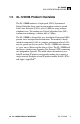
XL-12000B HIGH-SPEED NETWORK MODEM 1.0 XL-12000B Product Overview The XL-12000B modem is a high-speed, SDSL (Symmetrical Digital Subscriber Line) point-to-point modem created to extend Local Area Networks (LANs) up to 12,000 feet using ordinary telephone wires. The modem uses Digital Subscriber Line (DSL) transmission technology to deliver data at 2 Mbps. The XL-12000B is designed for easy installation. Front panel LEDs provide status and operational information.
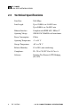
XL-12000B HIGH-SPEED NETWORK MODEM 2.0 2 Technical Specifications Data Rate: 2.048 Mbps Line Length: Up to 12,000 ft. on 24 AWG wire Up to 9,000 ft. on 26 AWG wire Ethernet Interface: Compliant with IEEE 802.
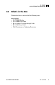
XL-12000B HIGH-SPEED NETWORK MODEM 3.0 What’s in the Box Confirm that there is one each of the following items: Description • XL-12000B Modem • XL-12000B User Guide • RJ-45 10Base-T Straight-through Cable • RJ-11 DSL Line Cable • Wall Transformer w/ Lightning Protection 3.
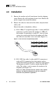
XL-12000B HIGH-SPEED NETWORK MODEM 4.0 Installation 1. Remove the modem and wall transformer from the shipping carton. Remove the wall transformer from its box. Remove the plastic wrapper from around the modem. 2. Remove the cable ties from each of the cables and place them side by side. Each of the cables is identified as follows: (1) RJ-45 10Base-T straight-through cable: A cable with RJ-45 connectors is used to connect the modem to a 10Base-T hub or node.
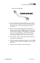
XL-12000B HIGH-SPEED NETWORK MODEM Figure 4.2 RJ-11 DSL Line Cable 2 5 3 3 4 4 5 2 3. Select a convenient location near the Ethernet device to which the modem will be connected. The modem should be kept away from excessive heat or cold. Operating temperature range is -5˚C to 55˚C. 4. Connect an RJ-45 straight-through cable from the 10Base-T Ethernet connector of the XL-12000B to an Ethernet device (PC, server, workstation or hub) as shown in Figure 4.3.
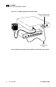
XL-12000B HIGH-SPEED NETWORK MODEM Figure 4.3 XL-12000B Installation with a Hub or Node. Ethernet Connection Switch in Normal (Hub) Position RJ-45 Straight-through Cable Note: The Ethernet connection switch facilitates use with either type of device. 6 TUT SYSTEMS 4.
XL-12000B HIGH-SPEED NETWORK MODEM 5.0 Panel Indicators and Connectors This section describes the indicators and connectors on the front and rear of the XL-12000B modem. 5.1 Front Panel Indicators Fig. 5.1 shows the LED indicators that provide status and operational information on the XL-12000B Modem. Power LED The blue Power LED remains lit while the unit has power. Activity LEDs The DSL RX and DSL TX LEDs flash green when receiving and transmitting data.
XL-12000B HIGH-SPEED NETWORK MODEM Figure 5.1 XL-12000B Front Panel DSL RX Flashing Green: On when receiving data. LI N K D SL ST AT US RX D SL TX DSL TX Flashing Green: On when transmitting data. D SL PO W ER POWER Blue MASTER SLAVE XL-12000B HIGH SPEED LAN MODEM STATUS Flashing Red: Power up self-test or software download in progress. 8 DSL LINK Steady Green: Normal link. Off: Normal condition. Flashing Green: Linking (about one minute). Steady Red: Board failure.
XL-12000B HIGH-SPEED NETWORK MODEM 5.2 Rear Panel Indicators and Connectors 10Base-T Link LED A green LED indicates a valid Ethernet link. When flashing, the LED indicates traffic on the link. When the LED is off, there is no valid link. Figure 5.2 XL-12000B Rear Panel 12VDC 10BASE-T LINK 10Base-T Link Green: Indicates valid Ethernet link. Flashing Green: Indicates activity. Off: No link. 10Base-T Ethernet Connection To connect to a PC, server, workstation, or hub. 5.
XL-12000B HIGH-SPEED NETWORK MODEM 6.0 10 Power and Boot Up Sequence 1. Verify that the LAN and DSL lines are connected according to the wiring diagram described in the “Installation” section (see Figure 4.3. 2. Plug the 120 VAC/12 VDC wall transformer (220VAC for international use) into a wall outlet. Verify that the Power (blue) LED comes on. 3. Verify that the 10Base-T Link (green) LED on the rear panel is illuminated. If the unit is not connected to an Ethernet (10Base-T) source (e.g.
XL-12000B HIGH-SPEED NETWORK MODEM 7.0 Troubleshooting This section is designed to assist in troubleshooting the XL-12000B. It also describes how to reach Technical Support at Tut Systems. Tut Systems takes pride in its products and would be more than happy to help with problems associated with the XL-12000B. Please take a moment and review the following answers to commonly asked questions before calling Technical Support. 1. The blue Power LED remains off.
XL-12000B HIGH-SPEED NETWORK MODEM 4. The DSL Link LED blinks for a long time. Blinking for a long time can indicate failure to communicate with the other modem within the acceptable noise parameters or that the distance between modems exceeds 12,000 feet. Verify the length of the DSL line and ensure it meets the length limits described in Appendix B. If it meets the limits, then have the line tested for defects. Another reason for continuous blinking is that both modems are either Masters or Slaves.
XL-12000B HIGH-SPEED NETWORK MODEM 8.0 Technical Assistance and Customer Support Maintenance and Repair Tut Systems offers a comprehensive range of customer support services, including technical assistance, installation, and maintenance agreements. For further information and pricing on Tut’s service products, contact your sales representative. Advance replacement, on-site, or remote technical support are all available 7 days a week, 24 hours a day through the Premier Maintenance Contract program.
XL-12000B HIGH-SPEED NETWORK MODEM Appendix A: Pinout Assignments Table A.1. RJ-45 10Base-T Ethernet Connector on Rear of Modem Pin # Mnemonic 1 Tx+ 10Base-T differential transmit signal (+) Function 2 Tx- 10Base-T differential transmit signal (-) 3 Rx+ 10Base-T differential receive signal (+) 4 NC Unused 5 NC Unused 6 Rx- 10Base-T differential receive signal (-) 7 NC Unused 8 NC Unused Note: Assumes the switch on the rear of the unit is in the “Normal” position. Table A.2.
XL-12000B HIGH-SPEED NETWORK MODEM Appendix B: Measure Line Length Measuring Phone Wire 1. Use a cable scanner or an ohmmeter to measure the lengths of phone wire that will connect the modems. When using an ohmmeter, short-circuit one end of the phone wire and measure the resistance between the two wires at the other end . Figure B.1 Using an Ohmmeter to Measure the Length of Phone Wire 600 Ohmmeter Short Pair Together OHMS Punchdown Block 2.
TUT SYSTEMS User Guide for the High-Speed Network Modem XL-12000B 2495 Estand Way, Pleasant Hill, CA 94523 800.998.4888 or 925.682.