XL-12000S Managed, High-Speed Network Modem USER GUIDE Start TUT SYSTEMS
Print Close Go to Table of Contents Quit
XL-12000S MANAGED, HIGH-SPEED NETWORK MODEM USER GUIDE Warranty Policy Warranty Summary This Tut Systems product is warranted against defects in material and workmanship and will substantially conform to Tut Systems product documentation for a period of one (1) year from the date of shipment.
XL-12000S MANAGED, HIGH-SPEED NETWORK MODEM USER GUIDE Changes or modifications not expressly approved by the party responsible for compliance could void the user’s authority to operate the equipment. The information contained in this publication is the latest available. However, Tut Systems reserves the right to change specifications of hardware and software without prior notice.
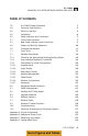
XL-12000S MANAGED, HIGH-SPEED NETWORK MODEM USER GUIDE Table of Contents 1.0 XL-12000S Product Overview 1 2.0 Technical Specifications 2 3.0 What’s in the Box 3 4.0 Installation 4 5.0 Panel Indicators and Connectors 7 5.1 Front Panel Indicators 7 5.2 Rear Panel Indicators and Connectors 6.0 Power and Boot Up Sequence 10 7.0 Configure the Modem 11 7.1 Quick Start 11 7.2 Detailed Procedures 14 7.2.1 Choosing the Appropriate Bridging/Routing Option 14 7.2.
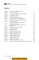
XL-12000S MANAGED, HIGH-SPEED NETWORK MODEM USER GUIDE Figures Figure 4.1 RJ-45 10Base-T Straight-through Cable 4 Figure 4.2 RJ-11 DSL Line Cable 5 Figure 4.3 XL-12000S Installation with a Hub or Node 6 Figure 5.1 XL-12000S Front Panel 8 Figure 5.2 XL-12000S Rear Panel 9 Figure 7.1 Serial Session/Version ID Screen 13 Figure 7.2 Bridging Example One (Basic Bridging) 15 Figure 7.3 Bridging Example Two (Advanced Bridging) 17 Figure 7.
XL-12000S MANAGED, HIGH-SPEED NETWORK MODEM USER GUIDE Tables Table 7.1 Keyboard Commands 27 Table 7.2 Specific Field Information for the Modem Management Screen 34 Table 7.3 Specific Field Information for the Modem Configuration Screen 37 Table 7.4 Specific Field Information for the Password Change Screen 40 Table 8.1 Specific Field Information for the SNMP Management Screen 42 Table 8.2 Specific Field Information for the DHCP Relay Agent Screen 44 Table 8.
XL-12000S MANAGED, HIGH-SPEED NETWORK MODEM USER GUIDE vi TUT SYSTEMS Back to Table of Contents
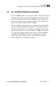
XL-12000S MANAGED, HIGH-SPEED NETWORK MODEM USER GUIDE 1.0 XL-12000S Product Overview The XL-12000S modem is a high-speed, SDSL (Symmetrical Digital Subscriber Line) point-to-point managed modem created to extend Local Area Networks (LANs) up to 12,000 feet using ordinary telephone wires. The modem uses Digital Subscriber Line (DSL) transmission technology to deliver data at 2 Mbps. The XL-12000S is designed for easy installation. Front panel LEDs provide status and operational information.
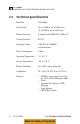
XL-12000S MANAGED, HIGH-SPEED NETWORK MODEM USER GUIDE 2.0 Technical Specifications Data Rate: 2.048 Mbps Line Length: Up to 12,000 ft. on 24 AWG wire Up to 9,000 ft. on 26 AWG wire Ethernet Interface: Compliant with IEEE 802.
XL-12000S MANAGED, HIGH-SPEED NETWORK MODEM USER GUIDE 3.0 What’s in the Box Confirm that there is one each of the following items: Description • XL-12000S Modem • XL-12000S User Manual • RJ-45 10Base-T Straight-through Cable • RJ-11 DSL Line Cable • Wall Transformer w/Lightning Protection • XL-12000S Enterprise SNMP MIB Diskette You will also need a PC with a serial port and a serial cable to connect to the modem’s point of connection, which is an RS-232 Console port (DB-9 female). 3.
XL-12000S MANAGED, HIGH-SPEED NETWORK MODEM USER GUIDE 4.0 Installation 1. Remove the modem and wall transformer from the shipping carton. Remove the wall transformer from its box. Remove the plastic wrapper from around the modem. a. Remove the cable ties from each of the cables and place them side by side. b. Each of the cables is identified as follows: (1) RJ-45 10Base-T straight-through cable: A cable with RJ-45 connectors is used to connect the modem to a 10Base-T hub or node.
XL-12000S MANAGED, HIGH-SPEED NETWORK MODEM USER GUIDE Figure 4.2 RJ-11 DSL Line Cable 2 5 3 3 4 4 5 2 2. Select a convenient location near the Ethernet device to which the modem will be connected. The modem should be kept away from excessive heat or cold. Operating temperature range is -5˚C to 55˚C. 3. Connect an RJ-45 straight-through cable from the 10Base-T Ethernet connector of the XL-12000S to an Ethernet device (PC, server, workstation or hub) as shown in Figure 4.3.
XL-12000S MANAGED, HIGH-SPEED NETWORK MODEM USER GUIDE Figure 4.3 XL-12000S Installation with a Hub or Node. Switch in Normal (Hub) Position -T 10BASE ET ETHERN E CONSOL 12VDC - + 10BASE LINK -T DSL ET ETHERNTION CONNEC NORMAL ECT RJ-45 CONN TO HUB CROSSED ECT RJ-11 CONN TO NODE RS-232 00S XL-120 10Base-T Cable Note: The Ethernet connection switch facilitates use with either a hub or node. 6 TUT SYSTEMS 4.
XL-12000S MANAGED, HIGH-SPEED NETWORK MODEM USER GUIDE 5.0 Panel Indicators and Connectors This section describes the indicators and connectors on the front and rear of the XL-12000S modem. 5.1 Front Panel Indicators Figure 5.1 shows the LED indicators that provide status and operational information on the XL-12000S Modem. Power LED The blue Power LED remains lit while the unit has power. Activity LEDs The DSL RX and DSL TX LEDs flash green when receiving and transmitting data.
XL-12000S MANAGED, HIGH-SPEED NETWORK MODEM USER GUIDE Figure 5.1 XL-12000S Front Panel DSL RX Flashing Green: On when receiving data. DSL TX Flashing Green: On when transmitting data. TUT SYSTEMS N S LI SL D X ST AT U RX SL SL T D D PO W ER K POWER Blue XL-12000S HIGH SPEED LAN MODEM STATUS Flashing Red: Power up self-test or software download in progress. DSL LINK Steady Green: Normal link. Off: Normal condition. Off: No link. Flashing Green: Linking (about one minute).
XL-12000S MANAGED, HIGH-SPEED NETWORK MODEM USER GUIDE 5.2 Rear Panel Indicators and Connectors 10Base-T Link LED A green LED indicates a valid Ethernet link. When flashing, the LED indicates traffic on the link. When the LED is off, there is no valid link. If this occurs, see section 10.0, “Troubleshooting”. Console Port The console port (RS-232) connects to a PC with a VT-100 terminal or PC VT-100 emulator for opening a management session. Figure 5.
XL-12000S MANAGED, HIGH-SPEED NETWORK MODEM USER GUIDE 6.0 10 Power and Boot Up Sequence 1. Verify that the LAN and DSL lines are connected according to the wiring diagram described in the “Installation” section (see Figure 4.1 or Figure 4.2). 2. Plug the 120 VAC/12 VDC wall transformer (220VAC for international use) into a wall outlet. Verify that the Power (blue) LED comes on. 3. Verify that the 10Base-T Link (green) LED on the rear panel is illuminated.
XL-12000S MANAGED, HIGH-SPEED NETWORK MODEM USER GUIDE 7.0 Configure the Modem This section provides two options for performing modem configuration. The “Quick Start” (section 7.1) option provides a basic Spanning Tree Protocol (STP) enabled bridge mode configuration with no remote management or password protection. The “Detailed Procedures” section (section 7.2) provides detailed steps covering all modes of modem operation.
XL-12000S MANAGED, HIGH-SPEED NETWORK MODEM USER GUIDE a. From the Windows 95/Windows 98 screen select “Start.” b. Select “Programs” (or Open file Hypertrm.exe). c. Select “Accessories.” d. Select “HyperTerminal.” When the HyperTerminal icon appears, double-click on it. e. On the Connection Description icon, assign a name (e.g. Modem1) to the icon for future purposes. Press “OK”. (When Phone Number tab appears, press “Cancel”.) f.
XL-12000S MANAGED, HIGH-SPEED NETWORK MODEM USER GUIDE 1. Go to the Call menu and select connect. You will see the Serial Session/Version ID screen (Figure 7.1). m. To verify that you have correctly configured your PC’s serial port, press the key and the XL-12000S Login Display screen (Figure 7.8) should appear. n. If your terminal remains blank, press and enter again. If it is still blank, make sure you have entered the correct settings in step seven above.
XL-12000S MANAGED, HIGH-SPEED NETWORK MODEM USER GUIDE 7.2 5. The XL-12000S units are now configured and the front panel indicators for the DSL link LED should start blinking as soon as the Master and Slave DSL ports are connected. If the DSL link LED does not blink, see the “Troubleshooting” section. 6. When link LEDs are solid green (after several minutes) the pair of modems are operational in bridging mode.
XL-12000S MANAGED, HIGH-SPEED NETWORK MODEM USER GUIDE The network design and table entries should be planned prior to filling out the static routing tables on the Modem Configuration screen. Routing table entries are also required for the gateway router and for the other routers reachable through the XL-12000S. 1. Basic Bridging In the bridge mode, the XL-12000S modem functions as a bridge connecting two parts of the same network. This selection allows the modem to pass both IP and non-IP packets.
XL-12000S MANAGED, HIGH-SPEED NETWORK MODEM USER GUIDE The configuration for the modems used in “Bridging Example One (Basic Bridging)”: LAN IP addresses are shown in Figure 7.2 although this option does not require you to enter new LAN IP addresses : Note: If all administration and configuration of the modems is to be done via the serial Console, as opposed to Telnet and SNMP sessions, no IP, mask, or default gateway addresses need to be assigned to the modems.
XL-12000S MANAGED, HIGH-SPEED NETWORK MODEM USER GUIDE Bridging Example Two (Advanced Bridging): This example shows how two pairs of XL-12000S units connect two LANs in separate buildings. It shows the best use of the Spanning Tree Protocol (STP) by creating redundant loops in the network. This way if one link becomes unavailable, STP uses the other path to reach the destination. This configuration is ideal when network availability is critical. Figure 7.
XL-12000S MANAGED, HIGH-SPEED NETWORK MODEM USER GUIDE The configuration for the modems used in “Bridging Example Two (Advanced Bridging)”: For Modem 1: The “LAN IP address” field in the Modem Management screen will be set to 192.168.1.8 The “Subnet Mask” field in the Modem Management screen will be set to 255.255.255.0 The “Default Gateway” field in the Modem Management screen will be set to a valid default gateway. The “Enable STP” field in the Modem Management screen is set to ‘Y’ (Default mode).
XL-12000S MANAGED, HIGH-SPEED NETWORK MODEM USER GUIDE For Modem 3: The “LAN IP address” field in the Modem Management screen will be set to 192.168.1.1 The “Subnet Mask” field in the Modem Management screen will be set to 255.255.255.0 The “Default Gateway” field in the Modem Management screen will be set to a valid default gateway. The “Enable STP” field in the Modem Management screen is set to ‘Y’ (Default mode). The “Master/Slave” field in the Modem Configuration screen will be set to Slave.
XL-12000S MANAGED, HIGH-SPEED NETWORK MODEM USER GUIDE 2. IP Routing Only This selection will route IP traffic between different networks. In “IP Routing Only” mode, the modem passes only IP packets between networks attached to the LAN and DSL sides of the modem, and networks designated in the modems static routing tables. This option will block all non-IP traffic. “Appendix D” provides subnet mask information.
XL-12000S MANAGED, HIGH-SPEED NETWORK MODEM USER GUIDE The configuration used for the modems in “Routing Example One (Using a Router and Bridge Combination)”: For Modem 1 (Router): The “LAN IP address” field in the Modem Configuration screen will be set to 192.168.2.2 The LAN “Subnet Mask” field in the Modem Configuration screen will be set to 255.255.255.0 The “DSL IP address” field in the Modem Configuration screen will be set to 192.168.3.
XL-12000S MANAGED, HIGH-SPEED NETWORK MODEM USER GUIDE Routing Example Two (Using a Router and Router Combination): This example shows two modems both with IP routing enabled. This configuration would be used to maximize the DSL bandwidth by eliminating unnecessary broadcast packet traffic on the DSL Link. Figure 7.5 Routing Example Two (Using a Router and Router Combination) Building 1 Building 2 Ethernet Hub 192.168.4.2 192.168.2.2 (LAN) 192.168.3.1 (DSL) 192.168.4.
XL-12000S MANAGED, HIGH-SPEED NETWORK MODEM USER GUIDE The static routing table fields in the Modem 1 Configuration would be: Destination 192.168.4.0 Mask 255.255.255.0 Gateway 192.168.3.2 Hops 1 For Modem 2: The “LAN IP address” field in the Modem Configuration screen will be set to 192.168.4.1 The LAN “Subnet Mask” field in the Modem Configuration screen will be set to 255.255.255.0 The “DSL IP address” field in the Modem Configuration screen will be set to 192.168.3.
XL-12000S MANAGED, HIGH-SPEED NETWORK MODEM USER GUIDE Figure 7.6 Bridge Non-IP Apple Printer Ethernet Hub 192.168.2.2 (LAN) TUT SYSTEMS 192.168.3.1 (DSL) 192.168.3.2 (DSL) Modem 1 TUT SYSTEMS Modem 2 192.168.4.1 (LAN) Ethernet Hub PC PC Mac The configuration used for the modems in “Bridge Non-IP” example: For Modem 1: The “LAN IP address” field in the Modem Configuration screen will be set to 192.168.2.2 The LAN “Subnet Mask” field in the Modem Configuration screen will be set to 255.255.
XL-12000S MANAGED, HIGH-SPEED NETWORK MODEM USER GUIDE The “Routing/Bridging” field in the Modem Configuration screen will be set to bridge_non_ip. The static routing table fields in the Modem 1 Configuration would be: Destination 192.168.4.0 Mask 255.255.255.0 Gateway 192.168.3.2 Hops 1 For Modem 2: The “LAN IP address” field in the Modem Configuration screen will be set to 192.168.4.1 The LAN “Subnet Mask” field in the Modem Configuration screen will be set to 255.255.255.
XL-12000S MANAGED, HIGH-SPEED NETWORK MODEM USER GUIDE • Planning network design and table entries prior to filling out the static routing tables on the configuration screen. • Obtaining the default gateway IP address, IP addresses for the LAN interface, and IP addresses for the DSL interfaces. 7.2.2 User Interface Keyboard Commands Now that a bridging/routing option has been chosen and a network plan has been completed, configure the pair of XL-12000S modems, as appropriate.
XL-12000S MANAGED, HIGH-SPEED NETWORK MODEM USER GUIDE is replaced with “Set Succeeded” or “Set Failed.” If invalid data is present in an input field, the system issues an error message and does not accept any data changes until the error is corrected. If changes have been made to fields that are marked with an (*), the modem will reboot when is pressed.
XL-12000S MANAGED, HIGH-SPEED NETWORK MODEM USER GUIDE 7.2.3 Procedures for Initial Configuration A serial console port session allows you to assign an IP address, mask, and default gateway to each new modem if required. Once installed and configured, you can open a Telnet session from a PC attached to a network that is connected to one of the XL-12000S LAN ports to configure further changes. Only one console session, either console port or Telnet based, can be open at one time.
XL-12000S MANAGED, HIGH-SPEED NETWORK MODEM USER GUIDE 7. Select a COM port (i.e., COM1) number and set the following parameters • • • • • 9,600 baud No-parity 8 data bits 1 stop bit None Press “OK”. 8. Under the File / Properties/ Settings: Set Function, Arrow, and Ctrl keys to act as Terminal Keys, Emulation - Auto detect. Backscroll buffer lines - 500. Press “OK”. 9. Set hardware flow control to none. You can set the display window to full screen size to avoid cutting off a section of the display.
XL-12000S MANAGED, HIGH-SPEED NETWORK MODEM USER GUIDE Figure 7.7 Serial Session/Version ID Screen The section continues by describing how to initially configure the modem via the Console port. 7.2.3.2 Login Display User Login At the Login Display the User Login field is presented. The user login refers to a class of user. Note: “Craft” is the only available user login and is displayed during login. The system login time is one minute.
XL-12000S MANAGED, HIGH-SPEED NETWORK MODEM USER GUIDE point press and proceed to the Main Menu to begin the initial configuration of your modem. Failed Login Attempts Once your system is password protected and a user enters an incorrect password, the user will not be able to access the system. Failed login attempts from a console or Telnet session are counted and the session is terminated after five attempts. You will be unable to access the system for a period of 60 seconds. Figure 7.
XL-12000S MANAGED, HIGH-SPEED NETWORK MODEM USER GUIDE 7.2.3.3 Main Menu Display From the main menu press “M” to continue with modem management. Figure 7.9 Main Menu Screen 7.2.3.4 Modem Management This procedure describes the configuration that is required to initialize your XL-12000S. The purpose is to set the modem’s IP address, default gateway, and subnet mask. Prior to completing this procedure, you will only be able to access your modem using a serial console connection.
XL-12000S MANAGED, HIGH-SPEED NETWORK MODEM USER GUIDE Figure 7.10 Modem Management Screen 1. Tab to the LAN IP Address field. Type the IP address of the modem’s LAN interface. 2. Tab to the Subnet Mask field. Type the subnet mask of the modem’s LAN interface. 3. Tab to the Default Gateway field. Type the IP address of the modem’s default gateway. 4. Entries may be made into optional fields at this time. See Table 7.2 for detailed descriptions of each field. 5.
XL-12000S MANAGED, HIGH-SPEED NETWORK MODEM USER GUIDE Table 7.2 Specific field information for the Modem Management screen. FIELD DESCRIPTION Date/Time If the Date field is not changed, (e.g. stays 01/01/70) the modem will keep track of the “uptime”. If the date is set to the appropriate date, time is expressed by a 24-hour clock. Time/Date values are not preserved over reboots. S/W Rev: Current software version running on the modem H/W Rev.: Current hardware version for the modem.
XL-12000S MANAGED, HIGH-SPEED NETWORK MODEM USER GUIDE FIELD DESCRIPTION Subnet mask: Enter the Subnet mask for IP address. Default gateway: Enter the IP address of the default gateway to which the modem LAN interface is connected. 7.2.3.5 Telnet Setup Use the following procedure to initiate a Telnet session once the initialization procedures described earlier in this section are complete.
XL-12000S MANAGED, HIGH-SPEED NETWORK MODEM USER GUIDE Figure 7.11 Modem Configuration Screen 36 1. The cursor is now blinking at entry for Master/Slave. The default setting is “S” for Slave. Designate only one modem in each pair to be the Master by entering “M” in this field. 2. Tab to the Name field (optional). Refer to the table for name parameters (see Table 7.3). Enter the name of the modem.
XL-12000S MANAGED, HIGH-SPEED NETWORK MODEM USER GUIDE 7. Tab to the Subnet Mask field for the DSL IP address. If option 1 or 4 was entered in the Routing/Bridging field, no entry is required. If option 2 or 3 is entered, enter the DSL subnet mask previously derived from your network planning. 8. Tab to the various Static Routing Table fields and fill in the appropriate values previously derived from your network planning. 9. Press to accept values. 10.
XL-12000S MANAGED, HIGH-SPEED NETWORK MODEM USER GUIDE FIELD DESCRIPTION Subnet Mask: (LAN and DSL) A mask selected by the Network Administrator to provide a specific subset of address numbers. A valid subnet mask is required for routing options 2 or 3. Enter 0.0.0.0 for default subnet mask setting. This address is used for a remote management session to the modem. DSL IP Address: (Right side of screen) A unique address number supplied by the Network Administrator for the DSL side of the modem.
XL-12000S MANAGED, HIGH-SPEED NETWORK MODEM USER GUIDE 7.2.3.7 Password This section provides instructions to secure your XL-12000S modems with password protection. When shipped, there is no password for the class of users known as “Craft”. Figure 7.12 Password Change Screen 1. From the main menu press “P” to access the password screen. 2. Tab to the New Password field. Enter a new password. A password may have up to 32 alphanumeric characters.
XL-12000S MANAGED, HIGH-SPEED NETWORK MODEM USER GUIDE After entering a new password or changing a password, we recommend you reboot your modem and verify you can log in using the new password. Table 7.4 Specific field information for the Password Change Screen FIELD DESCRIPTION Old password: Type in the current password. (If the modem has no password, tab to the New Password field.) New password: Type in the new password. A password may have up to 32 alphanumeric characters.
XL-12000S MANAGED, HIGH-SPEED NETWORK MODEM USER GUIDE 8.0 Advanced Modem Features The XL-12000S provides several advanced features: • • • 8.1 SNMP Management DHCP Relay Configuration Software Upgrade Capability SNMP Management The SNMP Management screen enables you to set up access to your XL-12000S modem via Simple Network Management Protocol (SNMP). If you are not familiar with SNMP, please consult your Network Administrator or consult SNMP reference material.
XL-12000S MANAGED, HIGH-SPEED NETWORK MODEM USER GUIDE The lower part of the screen designates which SNMP NMS stations will receive traps. Navigate to this screen by selecting “N” from the Main Menu. Figure 8.1 SNMP Management Screen Table 8.1 Specific field information for the SNMP Management screen. FIELD DESCRIPTION Community Name: Every agent must be configured to recognize one or more community names up to 20 characters. The default settings for communities are “public” and “private”.
XL-12000S MANAGED, HIGH-SPEED NETWORK MODEM USER GUIDE To return to the Main Menu without saving your changes, press . To access the modem via the Tut Enterprise MIB, load and compile the file “modem.MIB” from the enclosed floppy diskette to your NMS system. 8.2 Modem DHCP Relay Agent If Dynamic Host Configuration Protocol (DHCP) Relay is enabled, a DHCP session between a host connected to the XL-12000S modem and a server reachable by either the LAN or DSL ports of the XL-12000S may take place.
XL-12000S MANAGED, HIGH-SPEED NETWORK MODEM USER GUIDE 1. From the Main Menu select “D”. Note: Only one DHCP server address is supported for the DSL interface and one for the LAN interface. To broadcast to more than one DHCP server, leave the default (0.0.0.0) in place. Table 8.2 Specific field information for the DHCP Relay Agent screen. FIELD DESCRIPTION Enable DHCP Relay Agent (Y/N) Enables “Y” or disables “N” this feature. This feature has no meaning for a modem in bridged mode.
XL-12000S MANAGED, HIGH-SPEED NETWORK MODEM USER GUIDE To install a new version: 1. Ensure that image transfers are enabled on the Upgrade Software screen. The image currently not running will be the image replaced by the upgraded software. 2. Run the DOS program “tutxlutil” from the diskette provided by Tut Systems on a PC connected to the LAN to which the modems are connected (refer to page 46, “Detailed Steps for Running Tutxlutil”). 3.
XL-12000S MANAGED, HIGH-SPEED NETWORK MODEM USER GUIDE Figure 8.3 Upgrade Software Screen Table 8.3 Specific field information for the Upgrade Software screen. FIELD DESCRIPTION Running, Boot = > Image 1: Displays the currently running image (either 1 or 2). Displays the software release number of Image #1. Image 2: Displays the software release number of Image #2 or if empty, it will be blank. Choose image to Boot (1/2): Choose Image 1 or Image 2.
XL-12000S MANAGED, HIGH-SPEED NETWORK MODEM USER GUIDE First test connectivity by pinging from the PC to the IP address of the modem. To send the new image to an XL-12000S, invoke tutxlutil from the DOS command line as follows: tutxlutil /f upgrade-file [/u username] [/p password] target “Target” is the name or IP address of the target XL-12000S. If the username or password is not supplied, you will be prompted for it.
XL-12000S MANAGED, HIGH-SPEED NETWORK MODEM USER GUIDE 9.0 Modem Statistics The XL-12000S provides modem status and statistics. Note: Accessing these screens may effect modem performance during heavy use. To return to the main menu, press . 9.1 Modem Status This screen displays the expanded status detail for the selected modem. The DSL line state, Master/Slave selection, and modem name are on the top and modem network statistics appear on the bottom. Statistics are presented as “rolling totals.
XL-12000S MANAGED, HIGH-SPEED NETWORK MODEM USER GUIDE Table 9.1 Specific field information for the Modem Status screen. FIELD DESCRIPTION Master/Slave: Designates whether the modem is a Master or a Slave. State: Operating status of DSL line. Connect/disconnect. Name: The name assigned to the modem. Network Statistics Bytes Total: Modem LAN: Number of Ethernet bytes transmitted or received from the Ethernet link.
XL-12000S MANAGED, HIGH-SPEED NETWORK MODEM USER GUIDE 9.2 Modem IP Packet Statistics The Modem IP Packet Statistics screen provides information about IP packets processed by the modem. Select “K” from the Main Menu. Figure 9.2 Modem IP Packet Statistics Screen Table 9.2 Specific field information for the Modem IP Packet Statistics screen. 50 FIELD DESCRIPTION In Total: The total number of incoming IP packets received, including those received in error.
XL-12000S MANAGED, HIGH-SPEED NETWORK MODEM USER GUIDE FIELD DESCRIPTION In Delivers: The total number of incoming IP packets successfully delivered to IP user protocols (including ICMP). Forwards: The number of incoming IP packets for which the modem was not the final IP destination, and as a result, the modem tried to find a route to forward them to that final destination.
XL-12000S MANAGED, HIGH-SPEED NETWORK MODEM USER GUIDE 10.0 Troubleshooting This section is designed to assist in troubleshooting the XL-12000S. It also describes how to reach Technical Support at Tut Systems. Tut Systems takes pride in its products and would be more than happy to help with problems associated with the XL-12000S. Please take a moment and review the following answers to “commonly asked questions” before calling Technical Support. 1. The blue Power LED remains off.
XL-12000S MANAGED, HIGH-SPEED NETWORK MODEM USER GUIDE Both modems are configured as Masters or Slaves. Verify by checking both modems’ configurations in the “C” Modem Configuration screen. Make sure that one of the modems is a Master and the other is a Slave. Check all patch cables to be sure the pinout is correct and connections are well seated. 4. The DSL Link LED blinks for a long time.
XL-12000S MANAGED, HIGH-SPEED NETWORK MODEM USER GUIDE 6. Cannot Telnet to the modem. If an IP Address is assigned to one or both ports of the modem and Telnet access is not available this can be caused by three factors: First, check to be sure that the last serial console port session has been closed out by pressing from the Main Menu. Second, try to ping the modem’s IP Address. If you cannot ping the modem, then the PC does not know how to get to the modem.
XL-12000S MANAGED, HIGH-SPEED NETWORK MODEM USER GUIDE 8. SNMP cannot locate the modem. If your NMS is unable to find the XL-12000S modem during auto-discovery, try the following steps: 9. a. Try to ping the modem interface to determine if there is a network connection to the modem. If ping is still not working, double-check your network configuration (also see #9 below). b. Verify that the NMS “get” community name matches one of the modem’s configured community names.
XL-12000S MANAGED, HIGH-SPEED NETWORK MODEM USER GUIDE 10. I’m getting an error message when using tutxlutil. target: Host not found. No host named target was found. target: Connection refused. The target is not an XL-12000S. The target host exists, but does not appear to be an XL-12000S. May also happen with an XL-12000S if image transfer is not enabled. target: Connection timed out. Target is not responding to the network. Connection to target closed unexpectedly. The image was not completely sent.
XL-12000S MANAGED, HIGH-SPEED NETWORK MODEM USER GUIDE 11.0 Technical Assistance and Customer Support Maintenance and Repair Tut Systems offers a comprehensive range of customer support services, including technical assistance, installation, and maintenance agreements. For further information and pricing on Tut’s service products, contact your sales representative.
XL-12000S MANAGED, HIGH-SPEED NETWORK MODEM USER GUIDE Appendix A: Pinout Assignments Table A.1.
XL-12000S MANAGED, HIGH-SPEED NETWORK MODEM USER GUIDE Appendix B: Reference Screen Shots Figures 7.1 and 7.7 Serial Session/Version ID Screen (Pages 13 and 30 ) Figure 7.
XL-12000S MANAGED, HIGH-SPEED NETWORK MODEM USER GUIDE Figure 7.9 Main Menu Screen (Page 32 ) Figure 7.
XL-12000S MANAGED, HIGH-SPEED NETWORK MODEM USER GUIDE Figure 7.11 Modem Configuration Screen (Page 36) Figure 7.
XL-12000S MANAGED, HIGH-SPEED NETWORK MODEM USER GUIDE Figure 8.1 SNMP Management Screen (Page 42) Figure 8.
XL-12000S MANAGED, HIGH-SPEED NETWORK MODEM USER GUIDE Figure 8.3 Upgrade Software Screen (Page 46) Figure 9.
XL-12000S MANAGED, HIGH-SPEED NETWORK MODEM USER GUIDE Figure 9.
XL-12000S MANAGED, HIGH-SPEED NETWORK MODEM USER GUIDE Appendix C: Measure Line Length Measuring Phone Wire 1. Use a cable scanner or an ohmmeter to measure the lengths of phone wire that will connect the modems. When using an ohmmeter, short-circuit one end of the phone wire and measure the resistance between the two wires at the other end. Figure C.1 Using an ohmmeter to measure the length of phone wire. 600 Ohmmeter Short Pair Together OHMS Punchdown Block 2.
XL-12000S MANAGED, HIGH-SPEED NETWORK MODEM USER GUIDE Appendix D: Subnet Mask Table Below is a subnet mask table, which provides the following information: 1. Subnet mask expressed as a dotted decimal. 2. The number of total subnets along with the number of total hosts per subnet. 3. The network number, the IP address range, and the corresponding broadcast address. This netmask table only shows possible subnets of a Class C address.
XL-12000S MANAGED, HIGH-SPEED NETWORK MODEM USER GUIDE Subnet Mask: 255.255.255.240 Total of Subnets: 16 Subnet Hosts: 14 Network Address IP Address Range Broadcast Address .0 .1-.14 .15 .16 .17-.30 .31 .32 .33-.46 .47 .48 .49-.62 .63 .64 .65-.78 .79 .80 .81-.94 .95 .96 .97-110 .111 .112 .113-.126 .127 .128 .129-.142 .143 .144 .145-.158 .159 .160 .161-.174 .175 .176 .177-.190 .191 .192 .193-.206 .207 .208 .209-.238 .239 .240 .241-.254 .255 Subnet Mask: 255.255.255.
XL-12000S MANAGED, HIGH-SPEED NETWORK MODEM USER GUIDE Subnet Mask: 255.255.255.248 Total of Subnets: 32 Subnet Hosts: 6 Network Address IP Address Range Broadcast Address .232 .233-.238 .239 .240 .241-.246 .247 .248 .249-.254 .255 Subnet Mask: 255.255.255.252 Total of Subnets: 64 Subnet Hosts: 2 Network IP Address Broadcast Network IP Address Broadcast Address Range Address Address Range Address .0 .1-.2 .3 .140 .141-.142 .143 .4 .5-.6 .7 .144 .145-.146 .147 .8 .9-.10 .11 .148 .149-.150 .151 .12 .13-.14 .
TUT SYSTEMS User Guide for the Managed, High-Speed Network Modem XL-12000S 2495 Estand Way, Pleasant Hill, CA 94523 800.998.4888 or 925.682.