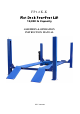
FP12K-K Flat Deck Four-Post Lift 12,000 lb Capacity ASSEMBLY & OPERATION INSTRUCTION MANUAL REV A-083013
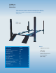
12,000 LB. FOUR POST CABLE LIFT Cable driven four post lift provides 12,000 lb. lifting capacity. No power beam; Cylinder stowed under single piece diamond plate track. Simple, lever release system and redundant safety locks. FP12K-K 12,000 lb.
TUXEDO DISTRIBUTORS LIMITED WARRANTY Structural Warranty: The following parts and structural components carry a five year warranty: Columns Legs Top Rail Beam Carriages Uprights Arms Swivel Pins Tracks Overhead Beam Cross Rails Limited One-Year Warranty: Tuxedo Distributors, LLC (“Tuxedo”) offers a limited one-year warranty to the original purchaser of Tuxedo lifts and Wheel Service in the United States and Canada.
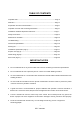
TABLE OF CONTENTS Important Note--------------------------------------------------------------------------------Page 3 Definition---------------------------------------------------------------------------------------Page 4 Preparation and General Information---------------------------------------------------Page 5 Important Concrete and Anchoring Information--------------------------------------Page 6 Installation and Basic Operation Instruction------------------------------------------Page 7 Safety Procedu
REV A-083013
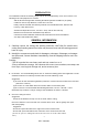
PREPARATION The installation of this lift is relatively simple and can be accomplished by 2 men in a few hours. The following tools and equipment are needed: AW 32,46 Non-Detergent Non-Foaming Anti-Wear Hydraulic Oil SAE-10 (12 quarts) Chalk line and 12’ Tape Measure, Transit and a 4’ Level Rotary Hammer Drill with 3/4” Masonry Drill Bit.
REV A-083013
REV A-083013
5. 6. Double check all dimensions and make sure that the layout is perfectly square. Before continuing with the installation it is helpful to stand the posts up at their respective locations and get a visual of the shop, aisles and other clearances. Also, this is a good time to drive a vehicle into position and check for adequate clearance. 7. NOTE All models MUST be installed on 3000PSI concrete only confirming to the minimum requirements.
REV A-083013
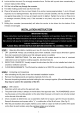
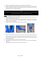
Fig. 13 Fig.14 Fig.15 2. Using bolts provided, bolt the right-rear end of the off-side runway on the rear cross bar. The other end is free. 3. Before locating the power-side runway on the cross bars, pull out the cables underneath and put them over the pulleys. The shorter one is for the power-side column. The longer one is for the offside column. 4. Take off the stop plate of the big pulley shaft on one end of cross bar. (See Fig.14) Take out the big pulley in order to let the cable go through it.
to size the wire for a 25 amp circuit. STEP 7: (Routing the CABLES) 1. Check again that all the cables are on the pulleys both of the columns and underneath the power-side runway. 2. Make sure that the current of the power supply is enough for the motor. 3. Press the start button on the motor to raise the runways a little. Make sure that the safety latches are not resting on the racks. 4. Screw the nut up or down on the column top to level the cross bar and runway.
REV A-083013
REV A-083013
REV A-083013
REV A-083013
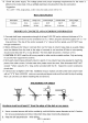
Packing List No Description Qty 1 Power-side runway 1 2 Off-side runway 1 3 Front cross bar 1 4 Rear cross bar 1 5 Power-side column 1 6 Off-side column 3 7 Column cover 4 8 Front stop 2 9 Approaching ramp 2 10 Long lock linkage rod 1 11 Beam cover 4 12 Accessory box 1 13 Electro-hydraulic pump 1 Note with cylinder ,hose and cables With lock release handle With mounting holes for pump Anchors and shims 14 15 16 17 18 19 20 21 22 INSTALLATION INSTRUCTION For FP12
ITEM Overall Width Inside Columns Inside Soleplate of columns Between Runways Length of Ramp Length of Runway Width of Outside runway Width of runway Size of Soleplate Overall Length Lifting Height Overall Height Length between Columns Lifting Capacity Net Gross Weight MODEL 165972 3120mm 2660mm 2560mm 928mm 910mm 4860mm 1980mm 482mm 280*280mm 4960mm 1760mm 2225mm 4500mm 12000lbs 1000 1050 kg A B C D E F G H I J K L M 16 REV A-083013
INSTALLATION INSTRUCTION Fig 3 (These data are suggestion not min.
INSTALLATION INSTRUCTION 18 REV A-083013 Fig 20
INSTALLATION INSTRUCTION 19 REV A-083013 Fig 21
FP12K-K Spare Parts List REV A-083013 ITEM DESCRIPTION QTY 1 2 3 4 4.1 4.2 4.3 5 6 7 7.1 7.2 7.3 7.
FP12K-K Spare Parts List REV A-083013 ITEM DESCRIPTION QTY 13 14 15 16 17 18 19 19.1 19.2 20 21 22 22.1 22.2 22.3 23 24 25 26 27 27.1 27.2 27.3 28 29 30 30.1 31 31.
FP12K-K Spare Parts List REV A-083013 ITEM DESCRIPTION QTY 6.1 6.5 6.6 6.7 6.8 6.9 6.11 6.12 6.13 6.14 6.17 6.18 6.19 6.21 10.1 10.2 10.3 11.
FP12K-K Spare Parts List ITEM DESCRIPTION QTY 33 34 35 35.1 36 37 38 38.1 39 40 40.1 41 41.1 41.2 41.3 41.
IMPORTANT POWER UNIT PRIMING PROCEDURE THE PROBLEM: Power unit runs fine but will not pump any fluid. Step 1 – Locate the check valve, the flush plug to the left of the lowering valve. (See drawing below.) Step 2 – Using an Allen wrench and shop towel – with shop towel in place to catch fluid – loosen the check valve plug 2 ½ turns to allow it to leak. Step 3 – Push the START button for one second, then release for three seconds. Repeat these steps until unit starts pumping fluid.