
Installation Guide
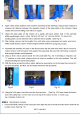
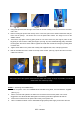


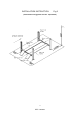

Fig. 13 Fig.14 Fig.15
2. Using bolts provided, bolt the right-rear end of the off-side runway on the rear cross bar. The other
end is free.
3. Before locating the power-side runway on the cross bars, pull out the cables underneath and put
them over the pulleys. The shorter one is for the power-side column. The longer one is for the
offside column.
4.
Take off the stop plate of the big pulley shaft on one end of cross bar. (See Fig.14) Take out the
big pulley in order to let the cable go through it. (See Fig. 15) Then reinstall the big pulley and fasten
the stop plate. Be sure that the cable is against the small roller so that the emergency locking latch
is off the rack.
5. Tighten all the bolts on the power-side runway with supplied bolts, nut
s, and spring washes.
6. Bolt the threaded end of the cable on the top of the column. (See Fig. 16)
Do the same for other
cables and columns.
Fig. 16 Fig.17 Fig. 18
SUGGESTION
Pull out the ram of the cylinder underneath the power-side runway as longer
as possible, to make the
cables reach the column top easily.
STEP 6: (Mounting the POWER UNIT)
1. Attach the power unit to the POWER-SIDE COLUMN using bolts, nuts and washers supplied.
(See Fig. 17)
2. Fill the reservoir with hydraulic oil. Make sure the funnel used to fill the power unit is clean.
Suggestion: Use AW 32,46 Non-Detergent Non-Foaming Anti-Wear Hydraulic Oil
SAE-10
3. Connect the oil hose from the power-side runway to the power unit.
4.
Have a certified electrician run the 220V/60Hz single phase power supply to the motor. Be sure
9
REV A-083013