
Installation Guide


to size the wire for a 25 amp circuit.
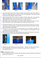
STEP 7: (Routing the CABLES)
1.
Check again that all the cables are on the pulleys both of the columns and underneath the
power-side runway.
2. Make sure that the current of the power supply is enoug
h for the motor.
3.
Press
the start button on the motor to raise the runways a little. Make sure that the safety latches
are not resting on the racks.
4.
Screw the nut up or down on the column top to level the cross bar and runway.
The cables should be checked weekly for equal tension. Failure to do this will cause uneven lifting. The
cables should always be adjusted so that they are equal tension when the cross bars are resting on the
safety locks.
IMPORTANT NOTE
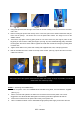
STEP 8: (Mounting on accessories)
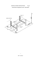
1.
Mount the front stops. (See fig. 18)
2.
Connect the long linkage rod from Front cross bar to rear cross bar. Make sure the safety locks
are working
correctly.
3. Route the hydraulic hose underneath the pow
er-side runway.
4. Mount on the approaching ramps.
5. Put the column covers on the column.
STEP 9: (Lift start up)
1. Do not place any vehicle on the lift at this time!
2.
Cycle the lift up and down several times to insure latch click together and all ai
r is removed from the
system.
3.
To lower the lift, the latch releases must be manually released while the lowering handle of the
pump
is pressed. Latches will automatically reset once the lift ascends approximately 17" from
the base.
OPERATION
RAISE-LIFT
1. Press button on power unit
The latch mechanism will ‘trip over’ when the lift
raises and drop into each latch stop. But, to lock the lift
you must press the lowering handle to relieve the hydraulic pressure and let the latch set tight in a lock
position.
Always lock the lift before going under the vehicle. Never allow anyone to go under the lift when
raising or lowering. Read the safety procedures in the manual.
10
REV A-083013