FP9K-DX-XLT Four Post Lift 9,000 lbs. Capacity (4,500 lbs.
READ THIS MANUAL THOROUGHLY BEFORE INSTALLING, OPERATING, OR MAINTAINING THIS LIFT. WHEN DONE WITH INSTALLATION BE SURE TO RETURN DOCUMENTS TO PACKAGE AND GIVE ALL MATERIALS TO LIFT OWNER/OPERATOR. WHEN INSTALLATION IS COMPLETE BE SURE TO RUN LIFT UP AND DOWN A FEW CYCLES WITH AND WITHOUT “TYPICAL” VEHICLE LOADED ON LIFT.
OWNER / EMPLOYER RESPONSIBILITY This is a vehicle lift installation/operation manual and no attempt is made or implied herein to instruct the user in lifting methods particular to an individual application. Rather, the contents of this manual are intended as a basis for operation and maintenance of the unit as it stands alone or as it is intended and anticipated to be used in conjunction with other equipment.
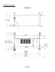
FLOOR PLAN LAYOUT FP9K-DX-XLT 4 FP9K-DX-XLT Jan 2019
TOOLS REQUIRED Ø Ø Ø Ø Ø Set of Metric Wrenches and/or Sockets Ø Phillips Screw Driver Adjustable Wrench Ø Rotary Hammer Drill (If anchoring) Locking Pliers Ø 3/4" Masonry Bit (If anchoring) 25’ Tape Measure Ø 3 Gallons of Hydraulic Oil* Step Ladder *Recommended Oil: ISO 32 Light Hydraulic Oil SELECTING SITE Before installing your new lift, check the following.
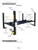
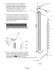
MAIN COMPONENTS IDENTIFICATION FP9K-DX-XLT Power Unit Column Column Sub Runway Drive-On Ramps (Not shown) Wheel Stop Drip Trays Crossbeam Jack / Tool Tray Mainside Runway Power Unit Poly Caster Kit Foot Step OPTIONAL ACCESSORIES NOT SHOWN: · RJ-45 Rolling Scissor Jack – 4,500 lbs.
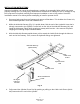
INSTALLATION INSTRUCTIONS Improper installation can cause accelerated wear, resulting in catastrophic failure which may cause property damage and / or bodily injury. Manufacturer will assume no liability for loss or damage of any kind, expressed or implied, resulting from improper installation or use of this product. Read this installation manual in its entirety before attempting to install or operate the lift. 1. Remove plastic wrap from top Runway and remove all hardware.
5. Now unbolt the top Mainside Runway (#3) taking the necessary safety precautions to support runway, as it will need to be flipped over. Note: Using some type of hoist is recommended to carefully flip the Runway over, so it’s no longer upside down. 6. Locate the Mainside Runway in your bay with the Hydraulic Fitting (#61) facing toward your previously chosen corner for the Power Unit. 7.
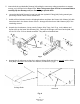
10. If you have means for securely lifting the Crossbeam, lower it into the tops of the Columns. If not, the Columns will have to be placed horizontally, in order to install the Crossbeams into the Columns. Then, the entire end structure (two columns and crossbeam) will need to be stood up as one. Top Cap Cable mount hole 11. Unpack the Lock Ladders (#11) (Fig. 5) from the package and slide them into the precut slot the Rub Blocks (#67) inside each column.
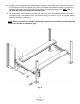
14. Stand up and arrange the two end structures (Columns & Crossbeams) so that the outside of the Crossbeam rail to the outside of the other Crossbeam rail measures 188.5”. Compare the measurements from the left and the right until they are diagonally within 1/2”. Note: The ½” variance will help in mounting the runways later. 15. Lift and position each Runway into place and secure to top of Crossbeams with the provided Hex Bolts (#24), Lock Washer (#25), Flat Washer (#26), as shown in Fig. 6.
16. Begin cable routing installation to Column Top Caps by first ensuring the pre-installed steel Cables are properly routed around each Cable Sheave and are not in a bind. Note: if Cable(s) comes off the Cable Sheave, it will be required to remove the Cable Sheave assembly to reinstall the Cable, due to welded cable guide brackets. 17.
18. Install Lock Rods & Linkage components per the drawing Fig.8. Also, install the Crossbeam Bracket (#96) to middle / outside of each Crossbeam and secure with the provided Hardware shown in Fig.6. Note: Crossbeam Linkage Rods may be pre-installed to Crossbeams. Also, ensure pre-installed T-Bar ‘linkage’ Rod is properly routed through guide ring weldments located on the underside of the Mainside Runway.
20. Install the “wire braded” Hydraulic Hose (#43) to the Fitting on the side of the Main side Runway and attach the other end to the 90 degree Fitting on the Power Unit as shown in Fig.2. 21. Now raise the complete unit (Lift) and set at one of the bottom lock positions. Place level on crossbeam. 22. Tighten Lock Ladder Rod Nut (#14) located on the top of each Column. This will raise the corner of the lift to adjust for leveling. Each Column has this adjustment. Adjust the proper columns to level the lift.
CASTER KIT ASSEMBLY INSTALLATION 1. Raise the Lift two to four feet high. 2. Assemble Caster assemblies as shown below. 3. Position each of the four Caster assemblies below the Crossbeam rails, as shown on page 6 and on Fig. 9. 4. Install the four Pivot Pins (#53) and Hairpin Cotter Pins (#52) to secure Caster assembly to each Column. 5. Lower the Lift confirming that the Caster assemblies engage the underside of Crossbeams and all four Columns rise to clear the floor.
FOUNDATION and ANCHORING REQUIREMENTS 1. Concrete shall have compression strength of at least 3,000 PSI and a minimum thickness of 4-1/4” in order to achieve a minimum anchor embedment of 3-1/4”. NOTE: When using the standard supplied 3/4” x 5-1/2” long anchors, if the top of the anchor exceeds 2-1/4” above the floor grade, you DO NOT have enough embedment. 2. Maintain a 6” minimum distance from any slab edge or seam. Hole to hole spacing should be a minimum 6-1/2” in any direction.
SAVE THESE INSTRUCTIONS SAFETY INSTRUCTIONS When using your garage equipment, basic safety precautions should always be followed, including the following: Ø Read all instructions Ø Care must be taken as burns can occur from touching hot parts. Ø Do not operate equipment with a damaged cord or if the equipment has been dropped or damaged until it has been examined by a qualified service person.
OPERATION INSTRUCTIONS NOTE: ALWAYS CHOCK WHEELS AND SET PARKING BRAKE BEFORE LIFTING VEHICLE! Read Safety & Operating Instructions procedures in Manual completely before operating lift. Ø Ø Ø Ø Ø Ø Ø Ø Ø Properly maintain and inspect lift in accordance to owner’s manual. Do not operate a lift that is damaged or in need of repair. Allow only authorized personnel in the lift bay. Stay clear of lift when raising or lowering (no riders). Keep hands and feet away from pinch points at all times.
PREVENTIVE MAINTENANCE SCHEDULE The periodic Preventive Maintenance Schedule given is the suggested minimum requirements & minimum intervals; accumulated hours or monthly period, whichever comes sooner. Periodic maintenance is to be performed on a daily, weekly, and yearly basis as given in the following paragraphs. Do not modify the lift in any manner without the prior written consent of the manufacturer.
TROUBLESHOOTING The common problems that may be encountered and their probable causes are covered in the following paragraphs: Ø Motor Does Not Operate: 1. Breaker or fuse blown 2. Faulty wiring connections 3. Defective up button WARNING!! Failure to properly relieve pressure in the following steps can cause injury to personnel. Ø Motor Functions but Lift Will Not Rise: 1. Power Unit is not priming correctly. (See Power Unit Prime Procedure on next page.) 2. A piece of trash is under release ‘down’ valve.
POWER UNIT PRIMING PROCEDURE THE PROBLEM: Power unit runs fine but will not pump any fluid. WARNING!! Failure to properly relieve pressure in the following steps can cause injury to personnel. Step 1 – Locate the check valve, the flush plug to the left of the lowering valve. Step 2 – Using an Allen wrench and shop towel – with shop towel in place to catch fluid – loosen the check valve plug 2 ½ turns to allow it to leak. Step 3 – Push the START button for one second, then release for three seconds.
LATCH & CABLE INSPECTION / ADJUSTMENTS WARNING!! Failure to perform routine inspections can lead to reduced service life, which could result in property damage and/or personal injury. Check locking latches for proper operation. Inspect for worn or missing parts. Replace worn or damaged parts and adjust as required. Ø Latch Mechanism Inspection Latches and Latch Bar Alignment: § Check for proper latch operation on all four corners.
EXPLODED VIEW #1 22 FP9K-DX-XLT Jan 2019
EXPLODED VIEW #2 23 FP9K-DX-XLT Jan 2019
EXPLODED VIEW #3 24 FP9K-DX-XLT Jan 2019
PARTS LIST FP9K-DX-XLT ITEM Tux P/N 1 2 3 4 5 6 7 8 9 9-1 10 11 12 13 14 15 16 17 18 19 20 21 22 23 24 25 26 27 28 29 30 31 31.1 32 33 34 35 36 37 FP9KDX-001 FP9KDX-002 FP9KDX-003 FP9KDX-004 FP9KDX-005 FP9KDX-006 FP9KDX-007 PU-110V-L-K FP9KDX-009 FP9KDX-009.
38 39 40 41 42 43 44 45 46 47 48 49 50 51 52 53 54 55 56 57 58 59 60 61 62 63 64 65 66 67 68 69 70 71 72 73 74 75 76 77 78 79 80 FP9KDX-038 FP9KDX-039 FP9KDX-040 FP9KDX-041 FP9KDX-042 FP9KDX-043 FP9KDX-044 FP9KDX-045 FP9KDX-046 FP9KDX-047 FP9KDX-048 FP9KDX-049 FP9KDX-050 FP9KDX-051 FP9KDX-052 FP9KDX-053 FP9KDX-054 FP9KDX-055 FP9KDX-056 FP9KDX-057 FP9KDX-058 FP9KDX-059 FP9KDX-060 FP9KDX-061 FP9KDX-062 FP9KDX-DT FP9KDX-JT FP9KDX-065 FP9KDX-066 FP9KDX-067 FP9KDX-068 FP9KDX-069 FP9KDX-070 FP9KDX-071 FP9KDX-072
81 82 83 84 85 86 87 88 89 90 91 92 93 94 95 96 97 98 99 100 101 102 103 FP9KDX-081 FP9KDX-082 FP9KDX-083 FP9KDX-084 FP9KDX-085 FP9KDX-086 FP9KDX-087 FP9KDX-088 FP9KDX-089 FP9KDX-090 FP9KDX-091 FP9KDX-092 FP9KDX-093 FP9KDX-094 FP9KDX-095 FP9KDX-096 FP9KDX-097 FP9KDX-098 FP9KDX-099 FP9KDX-100 FP9KDX-101 FP9KDX-102 FP9KDX-103 SY-8435T-5000-1 KY-8440T-5000-2 KY-8440T-2000-7 KY-8440T-2000-16 KY-8440T-2000-8 KY-8440T-2000-12 KY-8440T-2000-13 KY-8440T-2000-9 KY-8440T-2000-12-1 KY-8440T-2000-11 KY-8440T-2000-14
LIMITED WARRANTY Structural Warranty: The following parts and structural components carry a five year warranty: Columns Arms Uprights Swivel Pins Legs Carriages Overhead Beam Tracks Cross Rails Top Rail Beam Limited One-Year Warranty: Tuxedo Distributors, LLC (Tuxedo) offers a limited one-year warranty to the original purchaser of Lifts and Wheel Service equipment in the United States and Canada.