
Installation Guide

8
FP9K-DX-XLT
Jan 2019
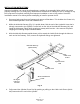
5. Now unbolt the top Mainside Runway (#3) taking the necessary safety precautions to support
runway, as it will need to be flipped over. Note: Using some type of hoist is recommended to
carefully flip the Runway over, so it’s no longer upside down.
6. Locate the Mainside Runway in your bay with the Hydraulic Fitting (#61) facing toward your
previously chosen corner for the Power Unit.
7. Unbolt all four Columns from the shipping brackets and place the Power Unit Column (#1) with
mount bracket in the above chosen corner. Arrange the other three Sub Columns (#2) in the
remaining corners.
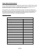
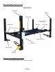
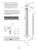
8. Unpack the Crossbeams, Cover panels, Ramps, Drip Trays, Jack Tray, Lock Ladders and
Caster Kit from the lower Sub Runway (#2). Remove the linkage rod Cover Panels (#68, #69,
#70 & #71) (Fig. 3) if not already removed. They will be reinstalled later.
Fig 3
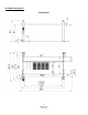
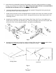
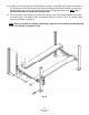
9. Arrange the Crossbeams so that the Latches’ Linkage Rods are facing outward and the Short
Rod (#83) is closest to the Power Unit Column, as shown in (Fig.4).
Linkage Rods
Fig. 4
Short Rod
Cover Panels