
Installation Guide

9
FP9K-DX-XLT
Jan 2019
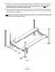
10. If you have means for securely lifting the
Crossbeam, lower it into the tops of the
Columns. If not, the Columns will have to be
placed horizontally, in order to install the
Crossbeams into the Columns. Then, the
entire end structure (two columns and
crossbeam) will need to be stood up as one.
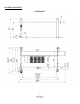
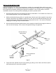
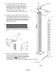
11. Unpack the Lock Ladders (#11) (Fig. 5) from
the package and slide them into the precut slot on
the Rub Blocks (#67) inside each column. After
removing the top Nut from the Lock Ladder,
you are ready to install the Top Caps A&B (#10 &
#65) on the columns.
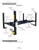
12. Be aware of the offset hole in column’s Top
Caps. Arrange Top Caps so that the cable
mounting holes are closest to the runways.
Use provided Bolts, Nuts, Washers and Lock
Washers to install Top Caps, as shown in Fig.5 &
5b.
Fig. 5b
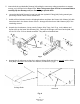
13. Secure Top Cap and Lock Ladder assemblies
together with Washer (#13) and Nut (#14) as
shown in Fig 5b. Note: Ensure Jam Nut (#12) is
positioned below Top Caps. Position the
Crossbeams at the second lowest locking position on all columns.
Fig. 5
Lock Ladder
Top Cap
Cable mount
hole