LR-26-PAD 6000 lb Capacity Low-Rise Pad Lift ASSEMBLY & OPERATION INSTRUCTION MANUAL REV A-090413
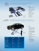
6,000 LB. LOW-RISE PAD LIFT Easy frame lifting on padded runways. Great for wheel and brake work, tire and wheel changing as well as new car preparation. Features: LR-26-PAD Low-rise Pad lift 6,000 LB. MID-RISE LIFT ✦ 6,000 lb. lifting capacity ✦ Automatic safety locks ✦ Low drive-over height for approach of low vehicles ✦ High speed motor lifts from 3”-26” in only 35 seconds ✦ 2 sets of rubber riser blocks Mid-rise models lift cars, vans and light-duty trucks.
TUXEDO DISTRIBUTORS LIMITED WARRANTY Structural Warranty: The following parts and structural components carry a five year warranty: Columns Legs Top Rail Beam Carriages Uprights Arms Swivel Pins Tracks Overhead Beam Cross Rails Limited One-Year Warranty: Tuxedo Distributors, LLC (“Tuxedo”) offers a limited one-year warranty to the original purchaser of Tuxedo lifts and Wheel Service in the United States and Canada.
INSTALLATION INSTRUCTION STEP 1: (Selecting Site) Before installing your new lift, check the following: 1. LIFT LOCATION: Always use architects plans when available. Check layout dimension against floor plan requirements making sure that adequate space is available. 2. OVERHEAD OBSTRUCTIONS: The area where the lift is to be located should be free of overhead obstructions such as heaters, building supports, electrical lines etc. 3.
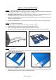
3. With the shims and anchor bolts in place, tighten by securing the nut to the base then turning 2-3 full turns clockwise. STEP 4: (Installing the MOTOR PUMP) 1. Assembly the wheel trolley according to Fig18. 2. Mount the motor pump (power unit) to the wheel trolley using bolts, nuts and washers supplied.(Fig. 5) Fig. 5 Fig.6 3. Take out the hose from the pad lift. Disconnect the hose fitting from the hose. (Fig. 6) 4. Screw the fitting to the motor pump outlet (Fig. 7). Connect the hose to the fitting.
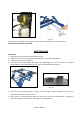
Fig. 10 Fig. 11 Cycle the lift up and down several times to insure all air is removed from the cylinder system. NOW THE LIFT IS READY FOR USE. PERFORMANCE RAISE-LIFT 1. Read operating and safety manuals before using lift. 2. Always lift a vehicle according to the manufacturers’ recommended lifting points 3. Position vehicle above the platform. 4. Insert the rubber locks between the vehicle and platform(Fig 12). ( There are two size of rubber blocks. Block 1st is 100*160*80H mm, the other is 100*160*H40 mm.
Note: It is normal for an empty lift to lower slowly-it may be necessary to add weight. LOWER LIFT 1. 2. 3. 4. 5. Be sure tool trays , stands or personal are removed from under lift. Raise the lift a little until the lock bar can be pulled aside. Pull the lock bar aside. Press the release handle at the power unit to lower the lift. Before removing vehicle from lift area, take out the rubber blocks to provide an unobstructed exit.
LIFT PARTS DRAWING AND PARTS CODE LIST 161106 Fig. 1 0100 FRAME Fig.
LR26-PAD / 161106 Fig. 1 0100 FRAME No. PART CODE DESCRIPTION QTY.
IMPORTANT POWER UNIT PRIMING PROCEDURE THE PROBLEM: Power unit runs fine but will not pump any fluid. Step 1 – Locate the check valve, the flush plug to the left of the lowering valve. (See drawing below.) Step 2 – Using an Allen wrench and shop towel – with shop towel in place to catch fluid – loosen the check valve plug 2 ½ turns to allow it to leak. Step 3 – Push the START button for one second, then release for three seconds. Repeat these steps until unit starts pumping fluid.