SP-6K-SS CAPACITY 6,000LB Single Post Storage Lift INSTALLATION & OPERATING INSTRUCTIONS Aug.
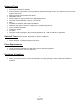
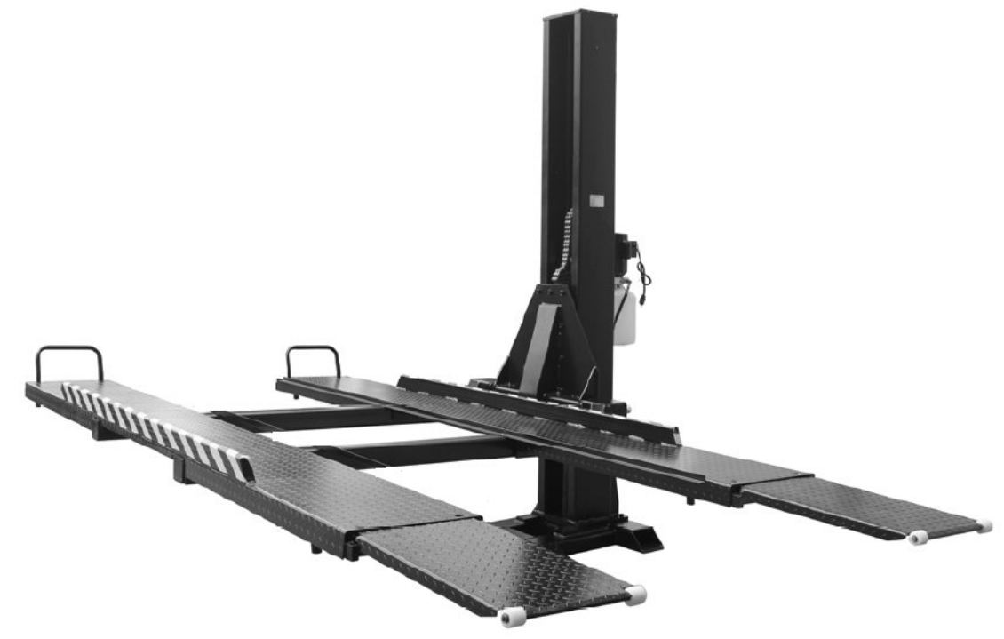
1. GENERAL INFORMATION 1.1 SPECIFICATIONS Specifications SP-6K-SS Capacity 6,000 lbs. Width Overall (pump mounted on back) 110-7/16” Width Overall (pump mounted on side) 106-5/16” Height Overall 110-1/4” Length Overall 185-13/16” Undercar clearance 76-15/16” Drive Over Base Ramp Height 3” Runway Width 18-7/8” Runway Length 151–15/16” Clearance Between Runways 39-3/8” – 42-1/2” Approach Ramp Length 30-3/4” Power Supply 110 VAC, 1PH, 20 Amp 2 Aug.
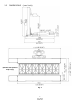
1.2 DIMENSIONS ( mm / inch) (Shown with optional Drip Trays) Fig. 1 3 Aug.
IMPORTANT! Be sure to read the operating instructions before operating Getting Ready Make sure you have made all necessary measurements to assure that your lift will fit in your garage and accommodate the two cars you intend to park with it. Make sure you have enough clearance at the top, and enough width to allow parking a third car on the non-lift side. It is useful to chalk the outlines of the lift on your garage floor, using the manufacturer’s dimensions, to see how the lift will fit.
Required Tools • • • • • • • • • • • • • Fork Lift to unload lift on delivery Fork Lift and/or engine hoist for moving pieces and positioning lift column. You will also need a ten-foot length of 3/8” chain Metric wrenches and sockets with ratchet Adjustable wrench Small crowbar or large screwdriver for aligning bolt holes Concrete hammer drill with a new ¾” concrete bit Pliers Flat blade screwdriver and Philips screwdriver.
Installation You will need common hand tools that most homeowners have, like a hammer, screwdrivers and pliers. But in addition, you will need some tools that are not common. Each installation is somewhat different, and depends on how much room you have to work around the lift. Here is a chronological sequence of installation steps, with the associated tools. 1. Unloading Lift You’ll need a forklift that can handle about 2500 to 3000 pounds and operate on a smooth surface.
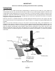
STEP 2 The next major piece is the lift column. It will have the carriage unit, the hydraulic cylinder and chain assembly, and safety latch cable already assembled in it. Pick column up from horizontal position by a forklift or an engine hoist. Carefully lift it vertically high enough to set the column on the base plate and maneuver it around to line up the mounting holes. The column is easier to maneuver when vertical on the base plate.
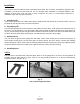
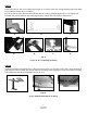
STEP 3 Before mounting motor pump, first mount the bracket on the side you preferred (Right or Left or Back). Then mount the motor pump on the back of column. Fix it using bolts and nuts. Connect the hose from the cylinder to the motor pump. (Fig.6 A, B, C) The hose has different fittings on each end. So make sure you match up the end of the hose with the cylinder. There is an O-ring on the end of the cylinder tube. Make sure these fittings are tight. Fig.
STEP 5 Position the two lift arms to the lifting frame (Fig.9 A). In order to make the runway platforms horizontal while car is loaded, install the arms as follows: First, lift up the far end of the arms with hydraulic jack to 3-15/16” (100mm) (Fig.9 B & C). Then tighten the back side two screws and front one screw (Fig.9 D & E). Use the lock-nut to secure adjustments. A D B E C F G Fig. 9 A, B, C, D, E, F, G (Setting-Up Arms) STEP 6 Install the runways on the lifting arms.
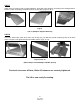
STEP 7 Attach drive-on ramps to end of runway platforms, along with ramp supports, according to the driving direction. Ensure Circlips are properly installed into slots on pivot pins. (Fig.11 A, B, C) Fig. 11 A, B, C (Ramps & Support Brackets) STEP 8 Put on the wheel stop at the other end of the runway (Fig. 12). Bolt the ground ramp fixing chip on the base plate. Then put on the ground ramps and middle spacer. (Figs. 13, 14) Figs.
OPERATING INSTRUCTIONS The lift is very simple to operate. Turn on the power supply first. Then press and hold the START button on the motor to activate it. The motor operates an internal pump that forces hydraulic oil into the lift cylinder, which extends the roller chain and raises the lift. (Fig.18) As the lift rises, an internal safety latch will pass over the steel stops (rectangular latch blocks which protrude from the back, inside of the lift column), and you will hear “clanks” as it does so.
RAISING A VEHICLE Drive the vehicle onto the platform through ramps until it is about centered. Set the parking brake. Depress the START button on power unit and the vehicle will rise. Raise the vehicle until it’s near the ceiling of the garage. WARNING!! BE CAREFUL NOT TO RAISE THE VEHICLE SO HIGH THAT IT STRIKES THE CEILING! MAKE SURE ANTENNAS ARE REMOVED, IF NECESSARY. ALSO BE AWARE OF ANYTHING THAT PROTRUDES FROM THE CEILING, LIKE LIGHTBULBS, GARAGE DOOR OPENERS OR DOOR TRACKS.
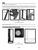
OPTIONAL ACCESSORIES The SP-6K-SS Lift has the ability to add Drip Trays between the Runways to assist in preventing any vehicle oil and/or debris from falling on the floor or another vehicle parked under the runways. NOTE: Drip Tray Rails are included with every SP-6K-SS Lift regardless if optional Drip Trays are applied or not. If Drip Trays are not to be used, it is not required to install the support Rails.
SP-6K-SS Exploded View (A) 14 Aug.
SP-6K-SS Exploded View (B) 15 Aug.
SP-6K-SS Parts list ITEM 1 2 3 3-1 4 5 6 7 8a-1 8a-2 9 10 11a 12 13 13-4 13-5 13-6 13-7 13-8 13-9 13-10 13-11 13-12 13-13 13-1 13-2 13-3 13-14 13-15 13-16 13-17 13-18 13-19 13-20 13-21 13-22 13-23 13-24 14 15 16 17 18 20 21 22 23 24 25 26 27 29 30 SP-6K-SS-001 SP-6K-SS-002 SP-6K-SS-003 SP-6K-SS-003.1 SP-6K-SS-004 SP-6K-SS-005 SP-6K-SS-006 SP-6K-SS-007 SP-6K-SS-008A.1 SP-6K-SS-008A.2 SP-6K-SS-009 SP-6K-SS-010 SP-6K-SS-011A SP-6K-SS-012 SP-6K-SS-013 SP-6K-SS-013.4 SP-6K-SS-013.5 SP-6K-SS-013.6 SP-6K-SS-013.
31 33 34 35 36 37 38 39 40 41 42 43 44 45 46 47 48 49 50 51 52 53 54 55 56 57 59 60 61 62 63 64 65 66 67 68 69 70 71 72 73 SP-6K-SS-031 SP-6K-SS-033 SP-6K-SS-034 SP-6K-SS-035 SP-6K-SS-036 SP-6K-SS-037 SP-6K-SS-038 SP-6K-SS-039 SP-6K-SS-040 SP-6K-SS-041 SP-6K-SS-042 SP-6K-SS-043 SP-6K-SS-044 SP-6K-SS-045 SP-6K-SS-046 SP-6K-SS-047 SP-6K-SS-048 SP-6K-SS-049 SP-6K-SS-050 SP-6K-SS-051 SP-6K-SS-052 SP-6K-SS-053 SP-6K-SS-054 SP-6K-SS-055 SP-6K-SS-056 SP-6K-SS-057 SP-6K-SS-059 SP-6K-SS-060 SP-6K-SS-061 SP-6K-SS-06
POWER UNIT PRIMING WARNING!! Failure to properly relieve pressure in the following steps can cause injury to personnel. IMPORTANT POWER UNIT PRIMING PROCEDURE THE PROBLEM: Power unit runs fine but will not pump any fluid. Step 1 – Locate the check valve. It is the plug to the left of the lowering valve. Step 2 – Using a Hex wrench and shop towel – with shop towel in place to catch fluid – loosen the check valve plug by approximately 2-½ turns and allow fluid to bleed off.
LIMITED WARRANTY Structural Warranty: The following parts and structural components carry a five year warranty: Columns Legs Tracks Arms Carriages Cross Rails Uprights Overhead Beam Top Rail Beam Swivel Pins Limited One-Year Warranty: Tuxedo Distributors, LLC offers a limited one-year warranty to the original purchaser of Lifts and Wheel Service equipment in the United States and Canada.