TP11KC-DX Two-Post Clear Floor ‘Bi-Symmetric’ Automotive Lift 11,000 lb. Capacity (2,750 lbs.
TABLE OF CONTENTS 1. Safety Information 1.1 Note, Caution and Warning 1.2 Important Information 1.3 Safety Instructions 2. Technical Manual 2.1 Product Description 2.2 Technical Data 3. Installation 3.1 3.2 3.3 3.4 3.5 Site Selection Surface Condition/ Foundation & Anchoring Tools Required Installation Procedure Hydraulic Scheme 4. Operation 4.1 4.1.1 4.1.2 4.1.3 4.1.4 4.1.5 4.1.6 4.
1. Safety Information 1.1 Note, Caution and Warning This document uses the following terms - NOTE, CAUTION and WARNING - to alert you to special instructions, tips, or hazards for a given procedure. Please familiarize yourself with the notations described below. INDICATES IMPORTANT INFORMATION THAT REQUIRES SPECIAL ATTENTION, SUCH AS A PROCEDURE FOR A SPECIFIC VEHICLE, OR TIPS ON OPERATING THE EQUIPMENT.
1.3 Safety Instructions 1. Do not raise a vehicle on the lift until the installation is completed as described in this manual. 2. Technicians should be trained to use and care for the lift by familiarizing themselves with this instruction manual. The lift should never be operated by an untrained person. 3. Always position the arms and adapters properly out of the way before pulling the vehicle into, or out of the bay. Failure to do so could damage the vehicle and/or the lift. 4. Do not overload the lift.
16. To reduce the risk of fire, do not operate equipment in the vicinity of open containers of flammable liquids. 17. Use the lift only as described in this manual, use only manufacturer’s recommended attachments. 18. Unusual vehicles, such as limousines, RV’s, and long wheelbase vehicles, may not be suitable for lifting on this equipment. If necessary, consult with the manufacturer or the manufacturer’s representative. 19.
2. Technical Manual 2.1 Product Description The TP11KC-DX (165948T) 2-post hydraulic lift is a surface mounted, frame contact lift incorporating the latest safety technologies. Designed and manufactured for a lifting capacity of 11,000 lbs. (Max 2,750 lbs. per Lifting Arm) and is fully capable for lifting vehicles, vans and light trucks by safely holding them in an elevated position.
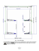
Fig. 1 – Front View Spec. POWER UNIT MUST BE INSTALLED ON THE PASSENGER SIDE. FAILURE TO DO SO CAN RESULT WITH INTERFERECE BETWEEN THE POWER UNIT AND SHORT SWING ARM, THUS CAUSING DAMAGE TO POWER UNIT.
Bi-Symmetric (Asymmetric & Symmetric) Configurations NOTE: Power Unit must be mounted on Passenger Side, beside the long/rear Swing Arm. Fig.2a –Top View Spec. Fig.2b - Base Size Spec.
3. Installation 3.1 Site Selection The hydraulic lift is designed only for indoor use. Application in a room with explosion hazard is not permitted. Setting in a wet place, a car wash center for instance, is prohibited. 3.2 Surface Condition / Foundation & Anchoring The 2-post hydraulic lift should be installed on level ground. The foundation must be 4-1/4” minimum thickness concrete, with a minimum compressive strength of 3,000 psi.
FOUNDATION and ANCHORING REQUIREMENTS, Fig 3 Drill holes using 3/4” carbide tipped masonry drill bit per ANSI standard B94.12.1977 Clean hole. Run nut down just below impact section of bolt. Drive anchor into hole until nut and washer contact base. 3.
3.4 Installation Procedure 1. Read this manual thoroughly before installing, operating, or maintaining this lift. 2. Site Evaluation and Lift Location: A. Always use an architect’s plan when provided. Before unpacking the lift entirely, determine if the site is adequate for the lift model being installed see figures 1 & 2 for typical bay layout and ceiling height requirements. B. Snap chalk lines to identify the lift’s centerline. C. Snap a chalk line parallel to the lift’s centerline, spaced 9.
5. Install Hydraulic Cylinders A. Install the cylinder to the cylinder mounts (uprights) with 9/16” x 4-1/2” pins, cylinder bushings (spacer) washers, and snap rings, as in figure 5a. The hose connecting port near the other end of the cylinder should be positioned pointing to the column’s opening. (Fig. 5b) B. Bolt the cylinder rods to the carriages. (Fig. 5c)NOTE: Make sure snap ring on cylinder rod is in groove. Fig. 5a Fig. 5b Fig.
Fig. 6a Fig. 6b Fig. 6c 8. Install overhead beam to cylinder mounts (uprights) using 2ea 1/2” x 1-3/4” bolts, washers & nuts on each end, (Figs. 7a, 7b, 7c). NOTE: Ensure overhead Limit Switch Assembly is on the Main side column side. Fig. 7a 13 TP11KC-DX Jun 2017 Fig.
Fig. 7c 9. Anchoring Off Side Column A. Using a level, check the alignment and plumbness of the entire structure. Plumb the off side column both side to side and front to back. B. The base of the column may vary from the preliminary layout, as it is more important that the column be perpendicular to the floor and parallel to the other column. C. Install the anchor bolts and shim the base as described in Step #6 10. Equalization Cable Routing A.
B. Using the diagrams, rout the equalization cables according to Fig. 8a, 8b, 8c from carriage to carriage through the cable rollers. Secure to carriages using Nylon Hex Nuts & Washers. Ensure that cables are not crossed together. Take out slack but DO NOT TIGHTEN CABLES AT THIS TIME. C. After equalizations cables are routed and connected to carriages, take out the slack in both cables by turning down the nuts on top of each carriage top.
11. Install the Hydraulic Fittings, Hoses and Return Lines A. Fitting & Hose Connecting: 1. First screw on the hose fitting connectors on the cylinder’s lower end ports. (Fig. 9a) 2. Connect the longest hose from the cylinder in Off side column to the top of Main side column. Remember to route the hose through the hook on cross beam. (Fig. 9b & 9c) 3. Then from the T-fitting inside column, connect the shortest length hose directly down to the main inside cylinder connector. (Fig. 9d) 4.
12. Mounting of the Power Unit A. Mount on the motor pump using 5/16” x 1-1/4” bolts and nylon nuts provided in the bolt box to Main side column. B. Connect the hose and the ‘blue’ Return Line to the pump valve block as shown in ( Fig 10) 13. Latch-release cable wiring and accessories mounting. A. Mount the safety latch device on each column as shown in ( Fig. 11a & 11b) Fig. 10 Fig. 11a Fig.
B. Mount the Cable Pulley and support bracket on the top of the columns. (Fig. 11c) Fig. 11c C. Route and adjust the cable tension so that when the handle is pressed down, both latch will be released. D. Put on the covers of the latch device. (Fig 12a & 12b) Fig. 12a Fig.
14. Install Lifting Arms A. Position the gears with pin against the bottom of the arms in the orientation shown in Fig.13a. Attach the gears to the arms with bolts. Do not tighten at this time. Fig. 13a Fig. 13b B. Position the restraint pawls on the carriage to mate with the gears on the arms. C. Install the swing arms and pins. Suggestion: The longer arms go to the rear or drive in side of the lift, and the short arms go to the front.
Fig. 14b - Rear Arm 15. Fill the Tank. Remove the vent plug from the power unit and fill the reservoir with hydraulic oil. Make sure the funnel used to fill the power unit is clean. Fill with Non-Detergent / Non-Foaming Hydraulic Oil - SAE-10, AW 32 or equivalent. Replace the vent plug. The unit holds approximately ten quarts of fluid. 16. Lubricate the four inside corners of both columns with heavy duty grease. 17. Electrical Connection to POWER UNIT & OVERHEAD LIMIT SWITCH A.
18. Testing (1) In this step A, there is no load on the lift. (2) Cycle up and down must be with interval rest of 2 min. A. Without a load, raise the lift empty to the top of its travel and lower it to the floor three (3) times to remove the remaining air from the hydraulic system. (IF POWER UNIT RUNS FINE BUT WILL NOT PUMP, SEE PAGE 32 FOR PRIMING PROCEDURE) B. The latches should click close together as the lift is being raised. If not, adjust the equalization cable by turn the nuts. C.
3.5 Hydraulic Scheme 1. Reservoir Tank 4. Motor 7. Hydraulic Cylinder(s) Motor Power Hydraulic Pressure Setting 2. Mesh Filter 5. Relief Valve 8. Manual Release Valve 3 HP @ 2,850 RPM 2,900 PSI 22 TP11KC-DX Jun 2017 3. Gear Pump 6. Check Valve 9.
4. Operation BE SURE TO READ AND FAMILIARIZE YOURSELF WITH THE SAFETY INSTRUCTIONS AT THE BEGINNING OF THIS MANUAL. FAILURE TO FOLLOW SAFETY INSTRUCTIONS MAY RESULT IN PROPERTY DAMAGE, PERSONAL INJURY OR DEATH. 4.1 Operating Instructions BE SURE TO READ AND FAMILIARIZE YOURSELF WITH THE SAFETY INSTRUCTIONS AT THE BEGINNING OF THIS MANUAL. FAILURE TO FOLLOW SAFETY INSTRUCTIONS MAY RESULT IN PROPER DAMAGE, PERSONAL INJURY OR DEATH.
d. Check support adapters for secure contact at vehicle manufacturer recommended lift points. e. Continue to raise to desired height only if vehicle is secure on lift. Then release the START button. f. DO NOT go under vehicle if all four adapters are not in secure contact at vehicle manufacture recommended lift point. g. Repeat complete spotting, loading and raising procedures if required. h. Press down the hydraulic pressure release lever on the motor pump to lower the vehicle into the locking position.
4.2 Maintenance Instructions Contact your service provider for instruction before starting up if you are not completely familiar with automotive lift maintenance procedures. Only qualified personnel can perform maintenance on this equipment. Any failure in operation may cause personal injury or death. Daily Always keep bolts tight. Check periodically. Always keep lift components clean. Always if oil leakage is observed, contact your service provider. Check cables and sheaves for wear every day.
5.
Parts List ITEM CODE DESCRIPTION QTY 1 165948T*01-001 column (offside) 1 2 165948T*01-002 socket screw 8 3 165948T*01-003 pad adapter (low) 4 4 165948T*01-004 pad adapter (high) 4 5 165948T*01-005 screw 26 6 165948T*01-006 roller 3 7 165948T*01-007 pin 1# 3 8 165948T*01-008 split pin 3 9 165948T*01-009 cover 2# 1 10 165948T*01-010 flat washer 8 11 165948T*01-011 small frame 1 12 165948T*01-012 bolt 2 13 165948T*01-013 nut 2 14 165948T*01-014 bolt 2
ITEM CODE DESCRIPTION QTY 37 165948T*01-037 air hose (2#) 1 38 165948T*01-038 column (main) 1 39 165948T*01-039 protect ring 1 40 165948T*01-040 cover 1# 1 41 165948T*01-041 handle ball 1 42 165948T*01-042 steel cable 2 43 165948T*01-043 handle 1 44 165948T*01-044 bearing 2# 2 45 165948T*01-045 oil hose 3# 1 46 165948T*01-046 T-type oil connector 1 47 165948T*01-047 oil hose 1# 1 48 165948T*01-048 oil hose 2# 1 49 165948T*01-049 carriage 2 50 165948T*
ITEM CODE DESCRIPTION QTY 73 165948T*01-073 rubber bar 2 74 165948T*01-074 straight arm 2 75 165948T*01-075 thin nut 2 76 165948T*01-076 nut 2 77 165948T*01-077 cylinder 2 77-1 165948T*01-077-1 piston rod 2 77-2 165948T*01-077-2 oil seal 2 77-3 165948T*01-077-3 O-ring 2 77-4 165948T*01-077-4 guide ring 2 77-5 165948T*01-077-5 steel ring 2 77-6 165948T*01-077-6 duct ring 2 77-7 165948T*01-077-7 circlips 2 77-8 165948T*01-077-8 O-ring 2 77-9 165948T*01-
ITEM CODE DESCRIPTION QTY 92 165948T*01-092 curved arm right 1 93 165948T*01-093 curved arm extension 1# 2 94 165948T*01-094 arm pin 4 95 165948T*01-095 circlips 4 96 165948T*01-096 slot 4 97 165948T*01-097 air hose (1#) 1 98 165948T*01-098 sponge bush 1 101 165948T*01-101 bolt 1 102 165948T*01-102 long screw slot 4 103 165948T*01-103 screw 4 104 165948T*01-104 fixing plate 2 105 165948T*01-105 Steel ring 4 106 165948T*01-106 Ripe grip 2 107 165948T*0
6. Troubleshooting Guide A. B. C D E F G H Problem Possible cause: 1. Blown fuse or circuit breaker. 2. Incorrect voltage to motor. 3. Bad wiring connections. 4. Motor up switch burned out. 5. Overhead limit switch burned out. 6. Motor windings burned out. Problem Possible cause: 1. Open lowering valve. 2. Pump sucking air. 3. Suction stub off pump. 4. Low oil level. Problem Possible cause: 1. Motor running on low voltage. 2. Debris in lowering valve. 3. Improper relief valve adjustment. 4.
7.
8.