
Installation Guide


11
TP11KC-DX
Jun 2017
3.4 Installation Procedure
1. Read this manual thoroughly before installing, operating, or maintaining this lift.
2. Site Evaluation and Lift Location:
A. Always use an architect’s plan when provided. Before unpacking the lift entirely, determine if the site is
adequate for the lift model being installed see figures 1 & 2 for typical bay layout and ceiling height
requirements.
B. Snap chalk lines to identify the lift’s centerline.
C. Snap a chalk line parallel to the lift’s centerline, spaced 9.00” (230 mm) toward the rear of the bay. This line
represents the back edge of the column bases.
D. Snap chalk lines parallel to the lift’s centerline spaced 68-7/8” (1,750 mm) to the left and 68-7/8”
(1,750 mm) to the right. These lines represent the APPROXIMATE outside edges of the column bases.
DO NOT USE THESE LINES TO POSITION THE COLUMNS, FOLLOW THE INSTRUCTIONS IN THIS
MANUAL.
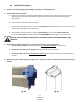
3. Unpack the lift. Remove the swing arms, bolt box, power unit box, and overhead beam.
A. Save all packing hardware, as these components are necessary to complete the installation.
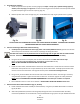
B. Remove the 1/2” bolts from the uprights which hold the two columns together.
C. Remove the upper column. Do not stand the columns up now but lay the columns with their flat backs on
the floor.
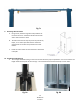
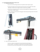
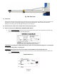
4. Attach the cylinder mounts (uprights) using 4ea 1/2” x 1-3/4” bolts, washers and nuts provided as shown in figure
4a & 4b.
Fig. 4a Fig. 4b