
Installation Guide


12
TP11KC-DX
Jun 2017
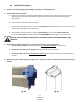
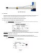
5. Install Hydraulic Cylinders
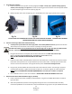
A. Install the cylinder to the cylinder mounts (uprights) with 9/16” x 4-1/2” pins, cylinder bushings (spacer)
washers, and snap rings, as in figure 5a. The hose connecting port near the other end of the cylinder should
be positioned pointing to the column’s opening. (Fig. 5b)
B. Bolt the cylinder rods to the carriages. (Fig. 5c)NOTE: Make sure snap ring on cylinder rod is in groove.
Fig. 5a Fig. 5b Fig. 5c
DO NOT HOLD THE CYLINDER ROD IN A WAY THAT COULD DAMAGE THE FINISH. CYLINDER LEAKS CAUSED BY
DAMAGED RODS ARE NOT COVERD UNDER WARRANTY.
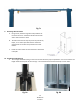
6. Columns Positioning & Main Side Column Anchoring
A. Carefully stand up the Main side column (w/ power unit bracket) & Off side column, position the columns
where they are to be secured. Ensure column’s openings are facing each other.
The Main side column must be positioned to be on the Passenger side or right side with the vehicle headed
forward. The distance between column back edge to wall, should be at least 2 feet for safety.
B. Using the column base as a template, drill the anchor bolt holes for the Main side column Only!
(Refer to FOUNDATION REQUIREMENTS & ANCHORING TIPS ON PAGES 9 & 10)
NOTE: DO NOT ANCHOR OFF SIDE COLUMN AT THIS TIME!
C. Install the anchor bolts, assemble washers & nuts onto the anchor bolts. Thread the nuts onto the anchors
bolts where the tops of the nuts are just above the top of the anchor bolts. Carefully tap the anchor bolts
into the concrete until the washer rests against the base plate. Ensure not to damage threads.
D. Using a level, plumb the Main side column both side to side and front to back. Shim the leg as necessary
using the Shims provided. Tighten anchor bolts to 130 ft. lbs. as noted on page 9. Re-check plumbness.
NOTE: Refer to FOUNDATION & ANCHOR REQUIREMENTS if more than 1/2” of shims are required.
E. Ensure Off side column is in the correct location. DO NOT DRILL HOLES FOR ANCHORS at this time.
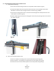
7. Overhead Limit Switch & Overhead Beam (Fig. 6a, 6b & 6c)
A. Install overhead limit switch assembly to overhead beam, using 2ea 1/4”-20 Bolt & Lock Nuts as shown in
figs 6a, 6b & 6c.
B. Slide end of padded bar (without a mounting hole) through the slot in the overhead switch assembly.
Connect the padded bar to the inside hole in the overhead beam using a spacer and 1/4”-20 Bolt & Lock Nut