
Product Manual

12
TP9KAC-TUX
Mar 2019
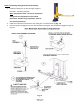
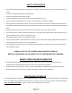
STEP 10: (Electrical Connection to POWER UNIT & OVERHEAD LIMIT SWITCH)
1. Have a certified electrician make the electrical connection to the power unit. Use a separate circuit for
each power unit, as shown below in (Fig. 14).
Fig. 14
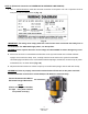
IMPORTANT! The wiring must comply with local code. Protect each circuit with time delay fuse or
circuit breaker. For 208V-230V single phase, use 20 amp fuse.
WARNING!! Never operate the motor in line voltage less than 208VAC as motor damage may occur.
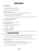
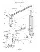
2. Secure one end of the overhead ‘shut-off’ limit wire to the eye bolt located on the offside column’s
upright, secure with wire clamp. Then, carefully route the loose end thru the eye bolt on mainside
column’s upright and down to the overhead limit switches’ plunger mechanism, located on top of power
unit’s switch box, as shown below (Fig. 14b).
3. Adjust the limit wire tension so it does not pull up on the kill switch plunger. Secure with wire clamp.
WARNING!! Failure to properly connect the overhead ‘shut-off’ limit wire to the power unit’s kill
switch mechanism could result in vehicle damage, lift damage or personal injury.
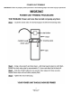
Fig. 14b
Connect Overhead Limit Wire to
Kill Switch Plunger Mechanism.
NOTE:
(Ensure not to adjust Limit Wire
too tight. If so, power unit will
not operate correctly.)