
Instruction manual


7
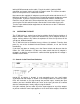
input you wish to associate with an output and press the appropriate output
button until the input signal you want appears on that output.
As selections are made, the LEDs will indicate your input selection plus
additional LEDs, to the right of the input selection LEDs will indicate whether
HDCP encryption is present on the selected input signal and if the signals are
HDMI or DVI compliant.
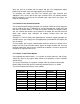
5.2 Control via the Infrared Controller
The included Infrared Remote Controller has a Power Switch at the top right that
can be used to turn the 1T-MX-6344 on and off. Beneath that switch you’ll find
four rows of selector buttons. The top row controls selections for output number
one, the second row controls input selections for output two and the third and
fourth rows control input selections for outputs number three and four
respectively.
Operation is similar to front panel operation but instead of stepping through the
available inputs, you simply press the appropriate input button for the output you
wish to control.
As an example, pressing the second button from the left on the second row of
buttons will cause input number two to appear on output number two. Pressing
the third button from the left on the second row of buttons will cause input three
to appear on output two and so on.
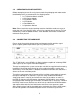
5.3 Control via the RS-232 Option
Using appropriate control codes, it is possible to switch power on and off plus
switch any input to any output under control of a computer or other hardware
control device.
To use this functionality, first prepare a control cable by reference to the table
below. Make certain that you have continuity between the pins as shown.
The RS-232 control connections are as follows:
1T-MX-6344 Controller
Pin Number Definition Pin Number Definition
1 NC 1 NC
2 Tx 2 Rx
3 Rx 3 Tx
4 NC 4 NC
5 GND 5 GND
6 NC 6 NC
7 NC 7 NC
8 NC 8 NC
9 NC 9 NC