
Instruction Manual

INSTALLATION 3-14 Manual 0-2708
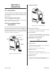
3.12 External Control Connections
External control signal connections can be made to the Rear
Panel of the power supply. Connections can be made to inter-
face with CNC Controls, Standoff Control SC11 or Remote Hand
Pendant.
Depending on the option installed determines how the option
is connected to the Power Supply.
A. Computer Control Interface (CNC)
NOTE
Used when Standoff Control SC11 are not used.
The computer control interface (CNC) allows an automated sys-
tem to interface with a computer or other control device.
CNC cables can be interfaced to the Power Supply using one of
the following methods:
NOTE
Refer to Appendix 6 for CNC Interface Schematic.
• Connector (J22) at the rear of the Power Supply
• Internal terminal block in the Power Supply
Depending on the equipment ordered and the cables supplied
connect the CNC cable per one of the following:
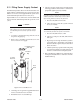
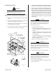
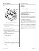
1. Using supplied CNC cable
Connect the supplied Power Supply/CNC Cable to the
Power Supply rear panel connector J22 (CNC Control).
A-02858
J22
CNC Connector
CNC or Remote Han
d
Pendant Control Cab
le
Figure 3-15 Using CNC Connector (J22)
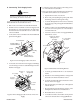
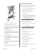
2. Using customer supplied CNC Cable
a. Remove the Right Side Panel from the Power Sup-
ply as viewed from the front of the unit.
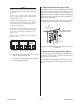
b. Remove the 7/8" knockout from the Rear Panel and
install a 1/2" NPT strain relief (not supplied) into
the hole.
A-02859
CNC Knockout
1/2" (12.7 mm)
Strain Relief
(Customer Supplie
d)
Figure 3-16 Rear Panel Knockout Location
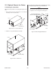
c. Locate the internal terminal block (TB) on the Fil-
ter/Voltage Divider PC Board, located on the inside
of Rear Panel below the WATER Secondary con-
nection. The terminal block (TB) is plugged into a
socket on the Filter/Voltage Divider PC Board.
d. Feed the CNC cable (see NOTE) through the strain
relief at the rear of the Power Supply, routing the
cable above the existing wiring to the Terminal Block
(TB) on the Filter/Voltage Divider PC Board.
NOTE
The CNC Cable to TB connections must be rated
at 600V.
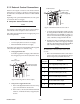
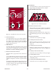
e. Remove the terminal block from the socket and con-
nect the CNC cable to the terminal block (TB) per
the following chart (see NOTES after chart):
TB
Connection
Description
1 Power Supply Output Voltage (ARC V +)
2 Power Supply Output Voltage (ARC V -)
3 High Side of START Signal (+15 vdc)
4 Low Side of START Signal (Common)
5 One Side of OK-To-Move Signal
6 Other Side of OK-To-Move Signal