
Instruction Manual

Manual 0-2708 4-1 OPERATION
SECTION 4:
OPERATION
4.01 Introduction
This section provides a description of the Power Supply
operating controls and procedures. Identification of the
Front and Rear Panel components is followed by operat-
ing procedures.
4.02 Functional Overview
The Power Supply provides a degree of operating flex-
ibility and the use of simple controls.
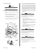
4.03 Front and Rear Panel
Descriptions
This sub-section provides specific functional descriptions
of the Power Supply front and rear panel operating con-
trols, indicators and connections. The Power Supply has
three main front panels and one rear panel. Each panel is
described in this sub-section as to the functions of the
connections, switches, and indicators.
Control/Acces
s
Panel
Lower Fro
nt
Panel
Rear
P
anel
A-02169
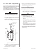
Gas Control Panel
Lifting Eye
Figure 4-1 Main Front Panels
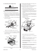
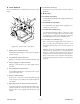
A. Lower Front Panel
1
2
A-02170
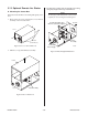
Figure 4-2 Lower Front Panel
1. Work Cable Strain Relief
Strain relief to secure the factory installed work cable
with ring terminal to the Power Supply.
2. Torch Leads Boot
Connection inside at the bulkhead for the Torch Leads
Assembly. The connections supply all the required
signals, gases, and coolant for the torch.
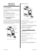
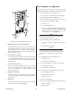
B. Control/Access Front Panel
NOTE
This panel is the access cover to the bulkhead area.
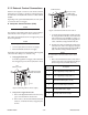
1. ON/OFF Switch
ON position activates all system control circuits when
remote or CNC enable is ON.
OFF position deactivates control circuits.
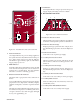
2. RUN/SET Switch
RUN position is used for torch operation.
SET position is used for setting gas pressures and
purging torch leads.
3. Current Control
Selects output current from 30-100 amps for the ap-
plication on various materials and thicknesses.