
Instruction Manual


Manual 0-2708 5-7 SERVICE
Troubleshooting With Optional Remote Arc
Starter
NOTE
The following troubleshooting is to be used only
if the system has the Optional Remote Arc Starter
installed.
Q. Start signal given to the Power Supply. Gas flows for
selected pre-flow time. DC Indicator is OFF, does not
even come ON momentarily.
1. Problem not in the Remote Arc Starter. The Power
Supply is has no DC voltage output.
a. Refer to the Power Supply Service Manual to test
the output of the Power Supply
R. Start signal given to Power Supply. Gas flows for
selected pre-flow time then DC Indicator is ON
steady. Pilot doesn't come on, but there is a spark
(repetitive snapping sound) from the spark gap in
Remote Arc Starter.
For the spark gap to fire, the Power Supply DC out-
put has to be getting to the Remote Arc Starter.
1. Consumable Torch parts are shorted
a. Check or replace the consumable Torch parts
2. Arcing or burning inside Torch Head Assembly
a. Remove the consumables from the Torch Head
Assembly and check for signs of arcing or burn-
ing inside the torch head. Replace Torch Head
Assembly if required.
3. Arcing or burning between the Torch fittings or from
the fittings to the Mounting Tube
a. Remove the Torch Head Assembly from the
mounting tube and check for arcing or burn-
ing between the fittings or from the fittings to
the tube. Repair as required.
4. Defective CD transformer
a. Check for arcing around the CD Transformer
(while spark gap is firing) and look for any
cracks in the ferrite cores. If either problem
exists replace the CD Transformer.
S. Start signal given to Power Supply. Gas flows for
selected pre-flow time then DC Indicator is ON
steady. Pilot doesn't come on and there is no
spark (no repetitive snapping sound) from the
spark gap in Remote Arc Starter.
1. Defective Remote Arc Starter PC Board
a. Refer to Section 5.06 Test Procedures to isolate
the defective assembly.
5.06 Test Procedures For Optional
Remote Arc Starter
WARNING
High voltage may be present in the Arc Starter
Box.
The following two things are needed for the spark gap to
fire in the Arc Starter Box:
• 36 VAC bias voltage
The 36 VAC should be present anytime the Power
Supply is turned ON. Refer to Appendix 6, 36 VAC
Circuit Diagram.
• Greater than 220 VDC Power Supply output
The Power Supply DC output should be greater
than 200 VDC when the Power Supply is activated
and the DC Indicator is ON. The voltage will be
present across the torch tip (+) and electrode (-).
The following procedure is to isolate the faulty assembly
to the Remote Arc Starter PC Board, Power Supply, Torch,
Torch Leads, or Torch Supply Leads Assembly
1. Remove the START signal from the power Supply to
disable the DC high voltage from the Remote Arc
Starter.
2. Place RUN/SET in SET position.
3. Power Supply DC Indicator is OFF.
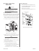
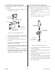
4. Remove cover from Remote Arc Starter.
5. On the Arc Starter PC Board locate the red Indicator.
When the Indicator is ON the 36 VAC between J1-1
and J1-3 on the Logic PC Board is present to the Arc
Starter PC Board.
NOTE
Connector J1 must be connected to the Arc Starter
PC Board.
• If red Indicator is ON proceed to Step 15.
• If red Indicator is OFF proceed to Step 6
6. Remove connector J1 from the Arc Starter PC Board
and reconnect making a good connection.
7. On the Arc Starter PC Board check the red Indicator.
• If red Indicator is ON proceed to Step 15.
• If red Indicator is OFF proceed to Step 8
8. Remove connector J1 from the Arc Starter PC Board.