00 208230V 400V 460V 600V CUTMASTER™ 102 PLASMA CUTTING SYSTEM Operating Manual Art # A-08618_AC Revision: AN Issue Date: February 10, 2014 Manual No.: 0-4997 VictorThermalDynamics.
WE APPRECIATE YOUR BUSINESS! Congratulations on your new Victor Thermal Dynamics product. We are proud to have you as our customer and will strive to provide you with the best service and reliability in the industry. This product is backed by our extensive warranty and world-wide service network. To locate your nearest distributor or service agency call 1-800-426-1888, or visit us on the web at www.VictorThermalDynamics.com.
! WARNING Read and understand this entire Manual and your employer’s safety practices before installing, operating, or servicing the equipment. While the information contained in this Manual represents the Manufacturer's best judgement, the Manufacturer assumes no liability for its use. Plasma Cutting Power Supply CutMaster® 102 SL100 1Torch™ Operating Manual Number 0-4997 Published by: Victor Technologies International, Inc. 82 Benning Street West Lebanon, New Hampshire, USA 03784 (603) 298-5711 www.
This Page Intentionally Blank
TABLE OF CONTENTS SECTION 1: GENERAL INFORMATION..............................................................................................1-1 1.01 1.02 1.03 1.04 1.05 1.06 1.07 1.08 Notes, Cautions and Warnings....................................................................1-1 Important Safety Precautions......................................................................1-1 Publications.................................................................................................
TABLE OF CONTENTS 4T.04 4T.05 4T.06 4T.07 4T.08 4T.09 Hand Torch Operation...............................................................................4T-3 Gouging.....................................................................................................4T-6 Mechanized Torch Operation....................................................................4T-7 Parts Selection for SL100 Torch Cutting...................................................
CUTMASTER 102 SECTION 1: GENERAL INFORMATION 1.01 Notes, Cautions and Warnings Throughout this manual, notes, cautions, and warnings are used to highlight important information. These highlights are categorized as follows: NOTE An operation, procedure, or background information which requires additional emphasis or is helpful in efficient operation of the system. CAUTION A procedure which, if not properly followed, may cause damage to the equipment.
CUTMASTER 102 • Repair or replace all worn or damaged parts. • Extra care must be taken when the workplace is moist or damp. • Install and maintain equipment according to NEC code, refer to item 9 in Subsection 1.03, Publications. • Disconnect power source before performing any service or repairs. • Read and follow all the instructions in the Operating Manual. PLASMA ARC RAYS Plasma Arc Rays can injure your eyes and burn your skin.
CUTMASTER 102 5. ANSI Standard Z41.1, STANDARD FOR MEN’S SAFETY-TOE FOOTWEAR, obtainable from the American National Standards Institute, 1430 Broadway, New York, NY 10018 ! 6. ANSI Standard Z49.
CUTMASTER 102 • Les sortes de gaz et de fumée provenant de l’arc de plasma dépendent du genre de métal utilisé, des revêtements se trouvant sur le métal et des différents procédés.
CUTMASTER 102 ! RAYONS D’ARC DE PLASMA Les rayons provenant de l’arc de plasma peuvent blesser vos yeux et brûler votre peau. Le procédé à l’arc de plasma produit une lumière infra-rouge et des rayons ultra-violets très forts. Ces rayons d’arc nuiront à vos yeux et brûleront votre peau si vous ne vous protégez pas correctement. • Pour protéger vos yeux, portez toujours un casque ou un écran de soudeur.
CUTMASTER 102 1.06 Documents De Reference Consultez les normes suivantes ou les révisions les plus récentes ayant été faites à celles-ci pour de plus amples renseignements : 1. OSHA, NORMES DE SÉCURITÉ DU TRAVAIL ET DE PROTECTION DE LA SANTÉ, 29CFR 1910, disponible auprès du Superintendent of Documents, U.S. Government Printing Office, Washington, D.C. 20402 2. Norme ANSI Z49.
CUTMASTER 102 1.07 Declaration of Conformity Manufacturer: Address: Victor Technologies 16052 Swingley Ridge Road, Suite 300 Chesterfield, MO 63033 USA Serial numbers are unique with each individual piece of equipment and details description, parts used to manufacture a unit and date of manufacture. National Standard and Technical Specifications The product is designed and manufactured to a number of standards and technical requirements.
CUTMASTER 102 1.08 Statement of Warranty LIMITED WARRANTY: Subject to the terms and conditions established below, Victor Technologies, Inc. warrants to the original retail purchaser that new Victor Thermal Dynamics CUTMASTER® plasma cutting systems sold after the effective date of this warranty are free of defects in material and workmanship. Should any failure to conform to this warranty appear within the applicable period stated below, Victor Technologies, Inc.
CUTMASTER 102 SECTION 2 SYSTEM: INTRODUCTION 2.02 Equipment Identification This Owner’s Manual applies to just specification or part numbers listed on page i. The unit’s identification number (specification or part number), model, and serial number usually appear on a data tag attached to the rear panel. Equipment which does not have a data tag such as torch and cable assemblies are identified only by the specification or part number printed on loosely attached card or the shipping container.
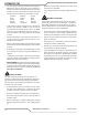
CUTMASTER 102 2.04 Power Supply Specifications CutMaster 102 Power Supply Specifications Input Power 208 / 230 VAC (187 - 253 VAC), Single Phase, 50/60 Hz 230 VAC (187 - 253 VAC), Three Phase, 50/60 Hz 380 VAC (360 - 440 VAC), Three Phase, 50/60 Hz 400 VAC (360 - 440 VAC), Three Phase, 50/60 Hz 460 VAC (414 - 506 VAC), Single Phase, 50/60 Hz 460 VAC (414 - 506 VAC), Three Phase, 50/60 Hz 600 VAC (540 - 630), Three Phase, 50/60 Hz Input Power Cable Power Supply includes input cable.
CUTMASTER 102 2.05 Input Wiring Specifications CutMaster 102 Power Supply Input Cable Wiring Requirements Input Freq Power Suggested Sizes voltage Input Volts Hz kVA I max I1eff Fuse Flexible Cord (amps) (Min. AWG) 1 208 50/60 20.6 99 76 100 4 Type W Phase 230 50/60 21.9 95 74 100 4 Type W 460 50/60 27.6 60 46 60 6 3 208 50/60 17.7 49 38 60 6 Phase 230 50/60 17.9 45 36 60 6 380 50/60 18.4 28 22 32 10 400 50/60 18.7 27 22 32 10 460 50/60 23.1 29 22 30 10 600 50/60 22.
CUTMASTER 102 2.
CUTMASTER 102 SECTION 2 TORCH: INTRODUCTION 10.125" (257 mm) 2T.01 Scope of Manual 3.75" (95 mm) This manual contains descriptions, operating instructions and maintenance procedures for the 1Torch Models SL100/Manual and SL100/Mechanized Plasma Cutting Torches. Service of this equipment is restricted to properly trained personnel; unqualified personnel are strictly cautioned against attempting repairs or adjustments not covered in this manual, at the risk of voiding the Warranty. Art # A-03322_AB 1.
CUTMASTER 102 2T.05 Introduction to Plasma Mechanized Torch Ratings Ambient Temperature 104° F 40° C Duty Cycle 100% @ 100 Amps @ 400 scfh Maximum Current 120 Amps Voltage (Vpeak) 500V Arc Striking Voltage 7kV A. Plasma Gas Flow G. Gas Requirements While the goal of plasma arc cutting is separation of the material, plasma arc gouging is used to remove metals to a controlled depth and width.
CUTMASTER 102 B. Gas Distribution E. The single gas used is internally split into plasma and secondary gases. The plasma gas flows into the torch through the negative lead, through the starter cartridge, around the electrode, and out through the tip orifice. The secondary gas flows down around the outside of the torch starter cartridge, and out between the tip and shield cup around the plasma arc. C. Pilot Arc Parts - In - Place (PIP) The torch includes a 'Parts - In - Place' (PIP) circuit.
CUTMASTER 102 This Page Intentionally Blank 2T-4 INTRODUCTION Manual 0-4997
CUTMASTER 102 SECTION 3 SYSTEM: INSTALLATION 3.01 Unpacking 1. Use the packing lists to identify and account for each item. 2. Inspect each item for possible shipping damage. If damage is evident, contact your distributor and / or shipping company before proceeding with the installation. 3. Record Power Supply and Torch model and serial numbers, purchase date and vendor name, in the information block at the front of this manual. 3.
CUTMASTER 102 3.04 Primary Input Power Connections CAUTION Check your power source for correct voltage before plugging in or connecting the unit. Check the Voltage Selector at the rear of the unit for correct setting before plugging in or connecting the unit. The primary power source, fuse, and any extension cords used must conform to local electrical code and the recommended circuit protection and wiring requirements as specified in Section 2.
CUTMASTER 102 6. Connect the wires as follows. • Connect Bus Bar Jumpers on the contactor as shown in prior illustration and on label in the power supply. • Green / Yellow wire to Ground. 7. With a little slack in the wires, tighten the through - hole protector to secure the power cable. 8. Reinstall the Power Supply cover per instructions found in section 5. 9. Connect the opposite end of individual wires to a customer supplied plug or main disconnect. 10.
CUTMASTER 102 3.05 Gas Connections Connecting Gas Supply to Unit The connection is the same for compressed air or high pressure cylinders. Refer to the following two subsections if an optional air line filter is to be installed. 1. Connect the air line to the inlet port. The illustration shows typical fittings as an example. NOTE For a secure seal, apply thread sealant to the fitting threads, according to manufacturer's instructions.
CUTMASTER 102 Regulator/Filter Assembly Inlet Port Art # A-07944 Hose Clamp 1/4 NPT to 1/4" (6mm) Fitting Gas Supply Hose Optional Single - Stage Filter Installation Installing Optional Two - Stage Air Filter Kit This optional two - stage air line filter is also for use on compressed air shop systems. Filter removes moisture and contaminants to at least 5 microns. Connect the air supply as follows: 1.
CUTMASTER 102 Regulator/Filter Assembly Regulator Input 2-Stage Filter Inlet Port (IN) Outlet Port (OUT) Two Stage Filter Assembly Hose Clamp Gas Supply Hose 1/4 NPT to 1/4” (6mm) Fitting Art # A-07945_AC Optional Two - Stage Filter Installation Using High Pressure Air Cylinders When using high pressure air cylinders as the air supply: 1. Refer to the manufacturer’s specifications for installation and maintenance procedures for high pressure regulators. 2.
CUTMASTER 102 SECTION 3 TORCH: INSTALLATION Check Air Quality To test the quality of air: 1. Put the ON / OFF position. 3T.01 Torch Connections If necessary, connect the torch to the Power Supply. Connect only the Thermal Dynamics model SL100 / Manual or SL100 / Mechanical Torch to this power supply. Maximum torch leads length is 100 feet / 30.5 m, including extensions. switch in the ON (up) 2. Put the Function Control switch in the SET position. 3.
CUTMASTER 102 Pinch Block Assembly Square Workpiece A-02585 Mechanical Torch Set - Up 3. The proper torch parts (shield cup, tip, start cartridge, and electrode) must be installed for the type of operation. Refer to Section 4T.07, Torch Parts Selection for details.
CUTMASTER 102 SECTION 4 SYSTEM: OPERATION 1 4.01 Front Panel Controls / Features MIN 2 A MAX See Illustration for numbering Identification 1. PSI BAR MAX MAX MIN MIN 4 + Output Current Control Sets the desired output current. Output settings up to 60 Amps may be used for drag cutting (with the torch tip contacting the workpiece) or higher for standoff cutting. 2. 3 ! Function Control Function Control Knob, Used to select between the different operating modes.
CUTMASTER 102 4.02 Preparations for Operation Power ON Place the Power Supply ON / OFF switch to the ON (up) At the start of each operating session: position. AC indicator turns ON. Gas indicator turns ON if there is sufficient gas pressure for power supply operation and the cooling fans turn ON. WARNING Disconnect primary power at the source before assembling or disassembling power supply, torch parts, or torch and leads assemblies.
CUTMASTER 102 Typical Cutting Speeds STANDOFF CutMaster 102 Gas Pressure Settings Leads Length SL100 SL100 (Hand Torch) (Mechanized Torch) Up to 25' (7.6 m) 75 psi 5.2 bar 75 psi 5.2 bar Each additional 25' (7.6 m) Add 5 psi 0.4 bar Add 5 psi 0.4 bar Cutting speeds vary according to torch output amperage, the type of material being cut, and operator skill. Refer to Section 4T.08 and following for greater details.
CUTMASTER 102 This Page Intentionally Blank 4-4 OPERATION Manual 0-4997
CUTMASTER 102 SECTION 4 TORCH: OPERATION 1. Unscrew and remove the shield cup assembly from the torch head. 2. Remove the Electrode by pulling it straight out of the Torch Head. 4T.01 Torch Parts Selection Torch Head Depending on the type of operation to be done determines the torch parts to be used. Electrode Type of operation: Drag cutting, standoff cutting or gouging Torch parts: Start Cartridge Shield Cup, Cutting Tip, Electrode and Starter Cartridge Tip NOTE Refer to Section 4T.
CUTMASTER 102 4T.02 Cut Quality Kerf Width The width of the cut (or the width of material removed during the cut). NOTE Cut quality depends heavily on setup and parameters such as torch standoff, alignment with the workpiece, cutting speed, gas pressures, and operator ability. Top Spatter (Dross) Cut quality requirements differ depending on application. For instance, nitride build - up and bevel angle may be major factors when the surface will be welded after cutting.
CUTMASTER 102 4T.04 Hand Torch Operation Direction of Cut In the torches, the plasma gas stream swirls as it leaves the torch to maintain a smooth column of gas. This swirl effect results in one side of a cut being more square than the other. Viewed along the direction of travel, the right side of the cut is more square than the left. Left Side Cut Angle Standoff Cutting With Hand Torch NOTE For best performance and parts life, always use the correct parts for the type of operation. 1.
CUTMASTER 102 Trigger Shield Cup Standoff Guide Trigger Release Torch Tip A-02986 5. Bring the torch within transfer distance to the work. The main arc will transfer to the work, and the pilot arc will shut OFF. Workpiece Art # A-04034 Shield Cup With Straight Edge The drag shield cup can be used with a non conductive straight edge to make straight cuts by hand. NOTE The gas preflow and postflow are a characteristic of the power supply and not a function of the torch.
CUTMASTER 102 3. Keep the torch in contact with the workpiece during the cutting cycle. 4. Hold the torch away from your body. 5. Slide the trigger release toward the back of the torch handle while simultaneously squeezing the trigger. The pilot arc will start. Piercing With Hand Torch 1. The torch can be comfortably held in one hand or steadied with two hands. Position the hand to press the Trigger on the torch handle.
CUTMASTER 102 7. Clean spatter and scale from the shield cup and the tip as soon as possible. Spraying the shield cup in anti - spatter compound will minimize the amount of scale which adheres to it. Cutting speed depends on material, thickness, and the operator’s ability to accurately follow the desired cut line. The following factors may have an impact on system performance: CAUTION Touching the torch tip or shield cup to the work surface will cause excessive parts wear.
CUTMASTER 102 Standoff Distance The tip to work distance affects gouge quality and depth. Standoff distance of 1/8 - 1/4 inch (3 - 6 mm) allows for smooth, consistent metal removal. Smaller standoff distances may result in a severance cut rather than a gouge. Standoff distances greater than 1/4 inch (6 mm) may result in minimal metal removal or loss of transferred main arc.
CUTMASTER 102 This Page Intentionally Blank 4T-8 OPERATION Manual 0-4997
CUTMASTER 102 4T.
CUTMASTER 102 4T.08 Recommended Cutting Speeds for SL100 Torch With Exposed Tip Type Torch: SL100 With Exposed Tip Type Plasma Gas: Air Thickness Inches Tip Output mm (Cat. No.) Volts(VDC) Type Material: Mild Steel Type Secondary Gas: Single Gas Torch Amperage Speed (Per Minute) Standoff Plasma Gas Press (Amps) Inches Meters Inches mm psi* bar Flow (CFH) Pierce Pierce Height Plasma Total** Delay (Sec) Inches mm 0.036 0.9 9-8208 104 40 340 8.64 0.19 4.8 65 4.5 55 170 0.00 0.
CUTMASTER 102 Type Torch: SL100 With Exposed Tip Type Plasma Gas: Air Thickness Inches Tip Output Type Material: Mild Steel Type Secondary Gas: Single Gas Torch Amperage Speed (Per Minute) mm (Cat. No.) Volts(VDC) Standoff Plasma Gas Press Inches mm Flow (CFH) Pierce Pierce Height (Amps) Inches Meters psi* bar 0.060 1.5 9-8210 110 60 290 7.37 0.19 4.8 70 4.8 Plasma Total** Delay (Sec) Inches mm 90 245 0.00 0.19 4.8 0.075 1.9 9-8210 120 60 285 7.24 0.19 4.8 70 4.
CUTMASTER 102 Type Torch: SL100 With Exposed Tip Type Material: Mild Steel Type Secondary Gas: Single Gas Torch Type Plasma Gas: Air Thickness Tip Inches mm 0.060 1.5 9-8211 0.120 3.0 9-8211 0.135 3.4 0.188 4.8 0.250 0.375 Output (Cat. No.) Volts(VDC) Amperage Speed (Per Minute) Standoff Plasma Gas Press Flow (CFH) Pierce Pierce Height (Amps) Inches Meters Inches mm psi* bar Plasma Total** Delay (Sec) Inches mm 113 80 320 8.13 0.19 4.8 65 4.5 115 340 0.00 0.
CUTMASTER 102 Type Torch: SL100 With Exposed Tip Type Material: Mild Steel Type Secondary Gas: Single Gas Torch Type Plasma Gas: Air Thickness Inches mm Tip Output (Cat. No.) Volts(VDC) Amperage Speed (Per Minute) Standoff Plasma Gas Press (Amps) Inches Meters Inches mm psi* bar Flow (CFH) Pierce Pierce Height Plasma Total** Delay (Sec) Inches mm 0.250 6.4 9-8212 110 100 105 2.65 0.190 4.8 75 5.2 130 390 0.4 0.200 5.1 0.375 9.5 9-8212 117 100 70 1.75 0.190 4.
CUTMASTER 102 4T.09 Recommended Cutting Speeds for SL100 Torch With Shielded Tip Type Torch: SL100 With Shielded Tip Type Plasma Gas: Air Thickness Inches Tip mm Output (Cat. No.) Volts (VDC) Type Material: Mild Steel Type Secondary Gas: Single Gas Torch Amperage Speed (Per Minute) Standoff Plasma Gas Press (Amps) Inches Meters Inches mm psi* bar Flow (CFH) Pierce Pierce Height Plasma Total** Delay (Sec) Inches mm 0.036 0.9 9-8208 114 40 170 4.32 0.19 4.8 65 4.5 55 170 0.
CUTMASTER 102 Type Torch: SL100 With Shielded Tip Type Plasma Gas: Air Thickness Inches mm Tip Output (Cat. No.) Volts(VDC) Type Material: Mild Steel Type Secondary Gas: Single Gas Torch Amperage Speed (Per Minute) Standoff Plasma Gas Press Flow (CFH) Pierce Pierce Height (Amps) Inches Meters Inches mm psi* bar 0.060 1.5 9-8210 124 60 250 6.35 0.19 4.8 70 4.8 90 245 0.00 0.2 5.1 0.075 1.9 9-8210 126 60 237 6.02 0.19 4.8 70 4.8 90 245 0.10 0.2 5.1 0.120 3.
CUTMASTER 102 Type Torch: SL100 With Shielded Tip Type Plasma Gas: Air Type Material: Mild Steel Type Secondary Gas: Single Gas Torch Thickness Tip Output Amperage Speed (Per Minute) Standoff Inches mm (Cat. No.) Volts(VDC) (Amps) Inches Meters Inches mm psi* bar 0.060 1.5 9-8211 128 80 280 7.11 0.19 4.8 65 4.5 115 340 0.00 0.2 5.1 0.120 3.0 9-8211 126 80 203 5.16 0.19 4.8 65 4.5 115 340 0.10 0.2 5.1 0.135 3.4 9-8211 128 80 182 4.62 0.19 4.8 65 4.
CUTMASTER 102 Type Torch: SL100 With Shielded Tip Type Plasma Gas: Air Thickness Inches mm Tip Output Type Material: Mild Steel Type Secondary Gas: Single Gas Torch Amperage Speed (Per Minute) Standoff Plasma Gas Press Flow (CFH) Pierce Pierce Height (Cat. No.) Volts(VDC) (Amps) Inches Meters Inches mm psi* bar 0.250 6.4 9-8212 124 100 110 2.80 0.180 4.6 75 5.2 130 390 0.4 0.200 5.1 0.375 9.5 9-8212 127 100 75 1.90 0.180 4.6 75 5.2 130 390 0.5 0.200 5.1 0.
CUTMASTER 102 PATENT INFORMATION Plasma Cutting Torch Patents The following parts are covered under U.S.
CUTMASTER 102 Catalog # Description Patent(s) 9-8245 Shield Cap US Pat No(s) 6914211; D496951 Other Pat(s) Pending The following parts are also licensed under U.S. Patent No.
CUTMASTER 102 This Page Intentionally Blank 4T-20 OPERATION Manual 0-4997
CUTMASTER 102 SECTION 5 SYSTEM: SERVICE 5.01 General Maintenance Warning! Disconnect input power before maintaining. Maintain more often if used under severe conditions Each Use Visual check of torch tip and electrode Weekly Visually inspect the torch body tip, electrode, start cartridge and shield cup Visually inspect the cables and leads.
CUTMASTER 102 5.02 Maintenance Schedule 5.03 Common Faults NOTE Problem - Symptom The actual frequency of maintenance may need to be adjusted according to the operating environment. Insufficient Penetration 1. Cutting speed too fast. 2. Torch tilted too much. 3. Metal too thick. 4. Worn torch parts 5. Cutting current too low. 6. Non - Genuine Thermal Dynamics parts used 7. Incorrect gas pressure Main Arc Extinguishes 1. Cutting speed too slow. 2. Torch standoff too high from workpiece. 3.
CUTMASTER 102 5.04 Fault Indicator At initial power up, two lights will temporarily illuminate for 2-3 seconds to show the version of software used. To determine the first digit, count the function indicators left to right, 1 through 5. To determine the second digit count the pressure indicators, reading from bottom to top, 0 through 7. In the example below the Temp indicator and 75 psi indicators are ON indicating the version would be 2.3.
CUTMASTER 102 5.05 Basic Troubleshooting Guide WARNING There are extremely dangerous voltage and power levels present inside this unit. Do not attempt to diagnose or repair unless you have had training in power electronics measurement and troubleshooting techniques. Problem - Symptom Possible Cause Recommended Action ON / OFF Switch is ON but the A/C Indicator does not light 1. Primary power disconnect is in 1. Turn primary power disconnect switch to ON position. OFF position. 2.
CUTMASTER 102 Problem - Symptom Possible Cause Recommended Action FAULT & 80 PSI indicators flashing. Gas flow is cycling ON and OFF. 1. Torch shield cup is loose. 2. Torch tip, electrode or starter cartridge missing. 3. Torch starter cartridge is stuck. 1. Tighten shield cup by hand. Do not overtighten. 2. Turn OFF power supply. Remove shield cup. Install missing parts. 3. Turn OFF power supply. Bleed down system pressure. Remove shield cup, tip and starter cartridge.
CUTMASTER 102 5.06 Power Supply Basic Parts Replacement C. Filter Element Assembly Replacement The Filter Element Assembly is in the rear panel. For better system performance, the filter element should be checked per the Maintenance Schedule (Subsection 5.02), and either cleaned or replaced. WARNING 1. Remove power from the power supply; turn OFF the gas supply and bleed down the system. Disconnect primary power to the system before disassembling the torch, leads, or power supply.
CUTMASTER 102 5. Remove the fitting from the filter element assembly by inserting a 6 mm hex wrench into the internal hex fitting and turning it counter clock-wise (left). Numbers 4 and 5 in the previous illustration. 1. Remove power from power supply. 6. Disconnect the input line from the filter element assembly. 3. Disconnect gas supply hose. 2. Shut OFF air supply and bleed down system before disassembling Filter to change Filter Element. 7.
CUTMASTER 102 Optional Two-Stage Filter Element Replacement 6. Slide the replacement Filter Elements into the Filter Assembly, with the same orientation as noted in Step 4 above. The Two-Stage Air Filter has two Filter Elements. When the Filter Elements become dirty the Power Supply will continue to operate but cut quality may become unacceptable. Refer to Section 6, Parts List, for replacement filter element catalog number. 7.
CUTMASTER 102 SECTION 5 TORCH: SERVICE Upper Groove with Vent Holes Must Remain Open 5T.01 General Maintenance NOTE Upper O-Ring in Correct Groove Refer to Previous "Section 5 System" for common and fault indicator descriptions. Threads Cleaning Torch Lower O-Ring Even if precautions are taken to use only clean air with a torch, eventually the inside of the torch becomes coated with residue. This buildup can affect the pilot arc initiation and the overall cut quality of the torch.
CUTMASTER 102 5T.02 Inspection and Replacement of Consumable Torch Parts Worn Tip Good Tip WARNING A-03406 Disconnect primary power to the system before disassembling the torch or torch leads. Example of Tip Wear 5. Remove the starter cartridge. Check for excessive wear, plugged gas holes, or discoloration. Check the lower end fitting for free motion. Replace if necessary. DO NOT touch any internal torch parts while the AC indicator light of the Power Supply is ON.
CUTMASTER 102 SECTION 6: PARTS LISTS 6.01 Introduction A. Parts List Breakdown The parts list provide a breakdown of all replaceable components. The parts lists are arranged as follows: Section "6.03 Power Supply Replacement" Section "6.04 Replacement Power Supply Parts" Section "6.05 Options and Accessories" Section "6.06 Replacement Parts for Hand Torch" Section "6.07 Replacement Parts - for Machine Torches with Unshielded Leads" Section "6.
CUTMASTER 102 6.04 Replacement Power Supply Parts Qty Description Catalog # 1 Regulator 1 Filter Assembly Replacement Element 1 Input Power Cord for 208 / 230 V Power Supply 1 460/600V Power Supply 9-0115 9-0116 9-0191 9-0209 6.
CUTMASTER 102 6.06 Replacement Parts for Hand Torch Item # Qty Description 1 1 Torch Handle Replacement Kit (includes items No. 2 & 3) 2 1 Trigger Assembly Replacement Kit 3 1 Handle Screw Kit (5 each, 6-32 x 1/2” cap screw, and wrench) 4 1 Torch Head Assembly Replacement Kit (includes items No.
CUTMASTER 102 6.07 Replacement Parts - for Machine Torches with Unshielded Leads Item No. Qty Description Catalog No. 1 1 Torch Head Assembly without leads (includes items 2, 3, and 14) 2 1 Large O-Ring 3 1 Small O-Ring 4 1 PIP Switch Kit 5 Unshielded Automated Leads Assemblies with ATC connectors 1 5 - foot / 1.5 m Leads Assembly with ATC connector 1 10 - foot / 3.05 m Leads Assembly with ATC connector 1 25 - foot / 7.
CUTMASTER 102 9 7 10 8 10 1 2 11 3 4 12 13 5&6 A-07994_AB Manual 0-4997 PARTS LIST 6-5
CUTMASTER 102 6.08 Replacement Shielded Machine Torch Leads Assemblies Item No. Qty Description 1 Mechanized Shielded Leads Assemblies with ATC Connectors 1 5 - foot / 1.5 m Leads Assembly with ATC Connector 1 10 - foot / 3.05 m Leads Assembly with ATC Connector 1 25 - foot / 7.6 m Leads Assembly with ATC Connector 1 50 - foot / 15.2 m Leads Assembly with ATC Connector Catalog No.
CUTMASTER 102 6.
CUTMASTER 102 This Page Intentionally Blank 6-8 PARTS LIST Manual 0-4997
CUTMASTER 102 APPENDIX 1: SEQUENCE OF OPERATION (BLOCK DIAGRAM) ACTION: ACTION: Close external disconnect switch. RESULT: Power to system. ACTION: ON / OFF switch to ON RESULT: AC indicator ON. GAS indicator ON when input pressure is adequate for power supply operation. Power circuit ready. RUN / Rapid Auto Restart / SET / LATCH switch to SET RESULT: Gas flows to set pressure.
CUTMASTER 102 APPENDIX 2: DATA TAG INFORMATION West Lebanon, NH USA 03784 Model : Dat e of Mf r : Type of Power Supply (Note 1) 1/ 3 f1 S/N Made in USA Regulatory Standard Covering This Type of Power Supply f2 Output Current Type Duty Cycle Factor Output Range (Amperage/ Voltage) Plasma Cutting Symbol X U0 = Rated NoLoad Voltage Duty Cycle Data (Note 3) I U2 Conventional Load Voltage Rated Maximum Supply Current Input Power Symbol U1 I 1max 3Ø 1 1Ø 1 1Ø I 1eff 3Ø Input Power Specifi
CUTMASTER 102 APPENDIX 3: TORCH PIN - OUT DIAGRAMS A. Hand Torch Pin - Out Diagram Negative / Plasma 8 - Open 4 - Green / Switch 3 - White / Switch Negative / Plasma 8 - Ground 4 - Switch 4 3 2- Orange / PIP 1 - Black / PIP ATC Female Receptacle Front View ATC Male Connector Front View 6 5 2 1 8 7 7 - Open 7 - Open 6 - Open 6 - Open 8 7 6 5 2 1 2 - PIP 5 - Open 5 - Open 3 - Switch 4 3 1 - PIP Pilot Pilot A-03701 B.
CUTMASTER 102 APPENDIX 4: TORCH CONNECTION DIAGRAMS A. Hand Torch Connection Diagram Torch: SL60 / SL100 Hand Torch Leads: Torch Leads with ATC Connector Power Supply: with ATC Receptacle Torch Head Male ATC Leads Connector ATC Female Receptacle Power Supply Torch Leads PIP Switch Torch Switch Black 1 1 Orange 2 2 5 5 6 6 Green 4 4 White 3 3 8 8 7 7 Negative / Plasma To Power Supply Circuitry To Power Supply Circuitry Negative / Plasma Pilot Pilot Art # A-03797 B.
CUTMASTER 102 This Page Intentionally Blank Manual 0-4997 APPENDIX A-5
CUTMASTER 102 APPENDIX 5: SYSTEM SCHEMATIC, 208/460V UNITS T1 3 C 1 2 3 4 5 4 2 PRI 4 PRI 3 J1 SW1 1 BIAS SUPPLY PRI 2 INRUSH RESISTORS +12VDC PRI 1 + TP2 MTH1 B A D PRI 2 PRI 1 + MTH2 TP1 K1 Q1 /INRUSH +12VDC BIAS SUPPLY D1 + TP8 L1 PRIMARY AC INPUT _ W1 L2 L3 GND L1 T1 L2 T2 L3 T3 L4 T4 MTH7 AC1 80A_AC1 AC2 80A_AC2 AC3 80A_AC3 MTH4 TP5 7 8 9 K1 K2 K3 K4 K5 K6 7A SW2 J3 * 460_IN 1 2 BUSS BARS/JUMPERS *PRIMARY POWER C3,C4,C7,C8* * CM102 & A80 C7
CUTMASTER 102 A120 ONLY 1TORCH TS1 PIP SWITCH L1 TORCH SWITCH 1 2 J11 SEC1 SEC2 +12VDC CHOKE1 ATC CONNECTOR J1 TEMP CIRCUIT 1 2 3 4 5 6 7 8 /OVERTEMP NTC -V OUT 1 1 2 3 4 5 6 7 8 E64 - E35 + AUTOMATION TORCH SOLENOID ELECTRODE1 D3 TIP1 Q5 PILOT IGBT WORK1 WORK J9 /PIP 1 2 3 4 5 6 7 /START 24VAC RETURN 24VAC SUPPLY 78 79 80 81 82 CNC INTERFACE STANDARD ON A80 & A120 UNITS CNC INTERFACE OPTIONAL ON CM102 & CM152 UNITS 83 J2 J10 1 2 3 4 5 6 7 8 OK-TO-MOVE (5A @ 250VAC / 30VDC) +
CUTMASTER 102 APPENDIX 6: SYSTEM SCHEMATIC, 600V UNITS 5 4 T1 3 2 C 1 2 3 4 5 4 PRI 4 PRI 3 J1 SW1 1 BIAS SUPPLY PRI 2 D INRUSH RESISTORS +12VDC PRI 1 + TP2 MTH1 B A D PRI 2 PRI 1 + MTH2 TP1 K1 Q1 EMI *CHOKE /INRUSH +12VDC BIAS SUPPLY D1 + C3,C4,C7,C8* UNITS * CEONLY TP8 EMI *FILTER L1 1 1 L2 2 2 L3 3 3 GND 4 4 _ W1 MTH7 AC1 80A_AC1 AC2 80A_AC2 AC3 80A_AC3 MTH4 TP5 7 L1 T1 8 L2 T2 L3 T3 L4 T4 9 7A 380/400/415V OR 600V 3 PH AC INPUT PRIMARY POWE
CUTMASTER 102 3 2 1 1TORCH TS1 PIP SWITCH L1 TORCH SWITCH 1 2 J11 SEC1 SEC2 +12VDC CHOKE1 ATC CONNECTOR J1 TEMP CIRCUIT 1 2 3 4 5 6 7 8 /OVERTEMP NTC -V OUT 1 1 2 3 4 5 6 7 8 E64 - E35 + AUTOMATION TORCH SOLENOID D ELECTRODE1 D3 TIP1 Q5 PILOT IGBT WORK1 WORK J9 /PIP 1 2 3 4 5 6 7 /START 24VAC RETURN 24VAC SUPPLY 78 79 80 81 82 CNC INTERFACE STANDARD ON A80 & A120 UNITS CNC INTERFACE OPTIONAL ON CM102 & CM152 UNITS 83 J2 J10 1 2 3 4 5 6 7 8 OK-TO-MOVE (5A @ 250VAC / 30VDC) +
CUTMASTER 102 APPENDIX 7: Publication History Cover Date May 30, 2008 Rev. AA Change(s) Manual released. June 23, 2008 AB Updated with new Cut Charts, updated system schematic per ECOB935 and added 460V version per ECOB939 Nov. 19, 2008 AC Updated system schematic. Jan 27, 2009 AD Corrected art sizing in section 3 to show missing information per ECOB1248. Updated power supply specs and input wiring charts in section 2 per ECOB1197. Apr.
This Page Intentionally Blank
THE AMERICAS Denton, TX USA U.S.